Calibration of the RPM sensor and conversion into a block wave .
To calculate the RPM , pulses of 5 V at a certain frequency have to be sent to the microcontroller . The number of pulses received by the microcontroller is then a measure for the RPM .
At first , we wanted to use a high resolution optical reflective sensor , more specifically the HBCS-1100 of HP .
The HBCS-1100
A Data sheet of this component can be found online at following address :
http://cp.literature.agilent.com/litweb/pdf/5966-1623E.pdf .
The problem with this kind of devices is that they are very sensitive to the dirt and grease that is present in the environment of the CFR . Another disadvantage is that this sensor only works well at a distance between 4,01 mm and 4,52 mm from the target . These are very small margins and since the set up of the CFR is subject to vibrations , the sensor risks to get into resonance so there would be a lot of noise on the output signal . Because of these problems , we decided to look for an alternative .
The solution was very simple : in the housing of the torque sensor , a connection for a whirl current collector is provided and there was a connector available in the labo . In the housing of the sensor , there is a cog wheel with 60 teeth . By adjusting the distance of the collector to the cog wheel , one can change the amplitude of the output signal of the collector . We placed it that way that the amplitude of the output signal is plus minus 14 V peak to peak .
This gives following signal on an oscilloscope :
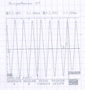
Not corrected signal from the RPM collector
This signal can’t be used by the microcontroller off course and the signal had to be converted into a block wave with pulses of plus minus 5 V , plus minus because it is allowed to have a certain margin on the input signal of the microcontroller . To achieve this block wave , we designed following network :
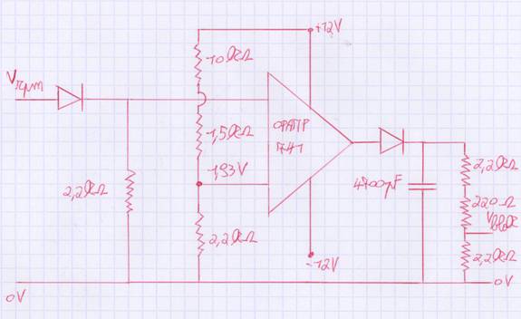
Network for RPM signal conversion
The signal from the collector is sent trough a diode to cut of the negative peaks . The first resistance is there to limit the currents that flow once the diode conducts . This signal is sent to the positive input of a comparator where it is compared with + 1,93 V from the negative input , that is formed from +12V via a tension divider , which results in either positive and negative pulses of 12 V since the OPAMP (LM 741) is fed by +12 V and -12 V . To cut off the negative pulses , another diode is placed just behind the comparator . Again resistances are placed to limit the currents that flow as soon as the diode conducts . These same resistances are used to make a tension divider which will convert the pulses of +12 V into pulses of +4,8 V .
The condensator is placed in parallel with the resistances to absorb the negative very small peaks which occurred because the diode is too slow to switch from conducting to blocking .
The width of the pulses is determined by the RPM . Since there are 60 teeth on the cog wheel , it suffices to count the number of pulses that are generated in 1 second and this immediately gives the number of revolutions in RPM instead of in Hz .
When we performed the final tests , we observed that the block wave was reduced to a practical 0V signal . This might have been due to the entrance impedance of the microcontroller . That is why we added an extra buffer behind the output signal . This is another OPAMP , namely a LM741 of which the positive input signal is the block wave and the negative input signal is the output signal of this same buffer freedbacked to the negative input . This small component solved the problem .
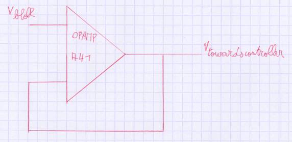
Buffer