The box .
Once all other hardware had been taken care off , we designed a box to put all the electronics in . The PCB was designed in that way to make sure that it fitted into the box , together with the microcontroller . The box was recuperated from an old plotter that didn’t work anymore . The old electronic circuits were taken out and the side panels removed . We made new side panels in aluminum with the right measures .
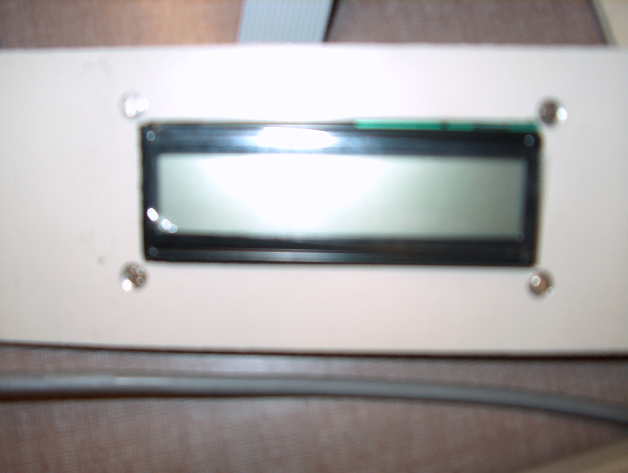
In front , we milled a hole where our display fits in and attached the display to the plate with screws . Because aluminum is an electric conductor , we placed a film of isolating plastic between the display and the plate .
The front side of the box
In the panel at the backside , we also drilled holes to attach connectors for the incoming signals and we glued labels next to the connectors so future users wouldn’t mistake between the different connectors . A BNC connector is placed for the RPM signal . A connector with 6 pins is placed for the analog voltage torque signal . And the 3 other connectors are for the sources of the microcontroller and the PCB , namely +12 V , -12 V and the ground .
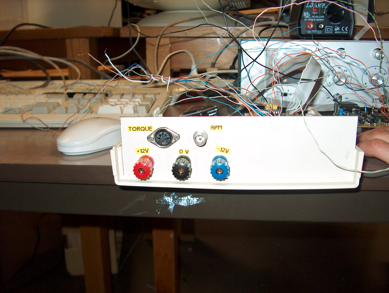
The back side of the box
We placed the box next to the already present magnifier so that both results can be compared . For this to be possible , we had to put some extra cables from the engine towards the box and from the amplifier towards the box . These cables were put in such a way that they don’t disturb anyone .