The print plate .
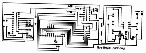
Because we have 3 different networks , namely the one for the RPM , the one for the ADC and the one for the shift registers , the entity is very unclear . That is why we decided to unify the 3 networks onto 1 print plate or PCB . This way , the number of cables is reduced to a minimum and they are replaced by cupper tracks . The PCB was first designed in a program called Traxmaker2 and then printed . After that , all missing components , such as diodes , capacities , resis-tances and missing connections were soldered on in specially drilled holes . The PCB was designed in such a way that it fits into the eventual box we made for this project . A very important factor that has to be paid attention to , is that all networks have the same common ground . Because of all the work that was performed on this plate , some of the cupper tracks had been damaged and some signals weren’t sent properly anymore . So we checked all the tracks with an Ohmmeter to see if there was a resistance between the points that were supposed to be linked . In case a resistance is present , it means the points aren’t galvanically linked and we soldered the damaged tracks . At the end of this process , all connections were repaired .
PCB made in Traxmaker2
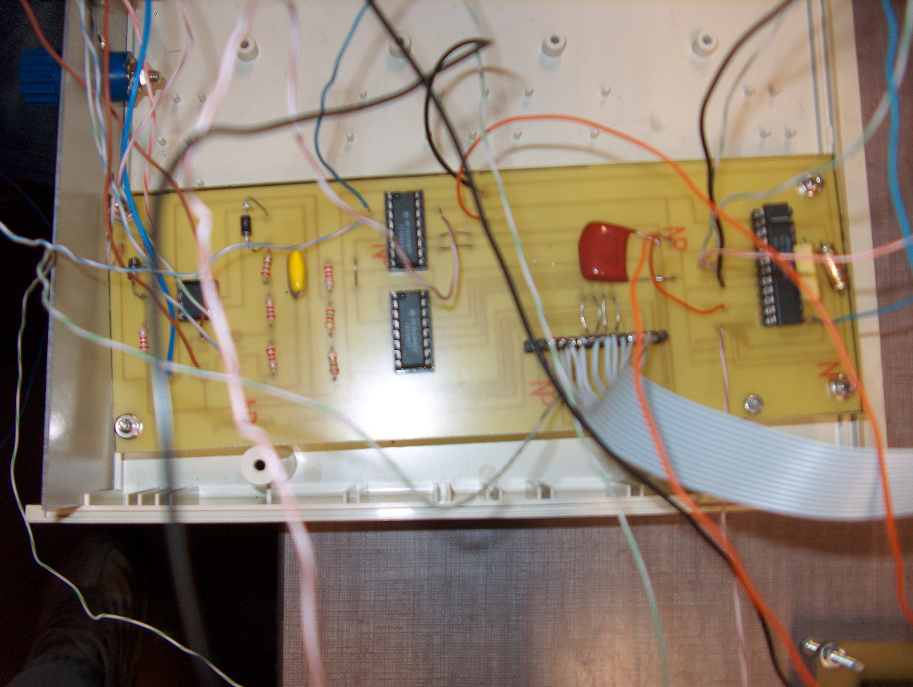
The actual print plate with cables and components