| Introduction :: Components :: Dowloads |
|
Before starting the Inventor drawing, it is important to know which components will be mounted on the robot. This seems evident but keep this in mind. To make sure you wonĺt have to start over, this is a very important issue. Make sure that all components are chosen carefully and that the signal processing of the sensors is working (a signal between 0 and 5 Volts) before starting the 3D drawing. Also make a sketch of the location of the components before starting in Inventor. [ top ] |
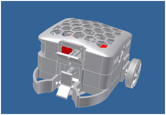
In our design, the following components are build in:
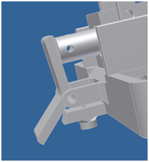
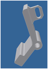
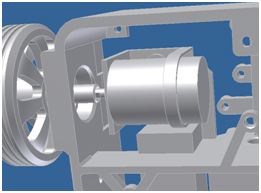
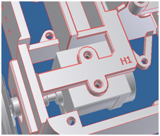
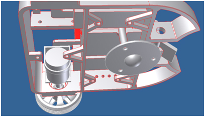
Solenoid (actuator) to kick the ball away
This component is very large. Because we decided to late to mount this component we had many difficulties to build this one in. Before you use this component see that the location is known at the beginning of the drawing and that you choose a good location. Our solenoid was a pull type. A push type would be more convenient but it is hard to find one. We made a lever system to work with the pull type to transfer the movement to the ball. Actually, this was a good system to give an extra acceleration to the ball.
|
|
Infrared detection sensors to locate the ball
When you use these sensors, keep in mind that the sun also emits infrared light. If the program is made to accurate, this could result in some problems. In our design we used one horizontal IR sensor on the front to detect the location of the ball. A second is mounted under a specific angle. This sensor is used to determine that the ball is in front of the robot. It would be better if this sensor was mounted vertically and if it was covered from lateral radiation.
 |
Sharp distance sensors for sidedetection
In de design of the robot the non-linear response of the IR-sensor was taken into account. As the sensor has it detection peak around 10cm, the sensors were placed in exactly this distance to overcome this peak response (as can be found in the datasheet of the sensor).
 |
 |
Grayscale sensors
These sensors are installed on the bottom side of the robot, at a distance of 4mm above the ground, to optimize the response of the sensor and minimize the value of the measure-resistor (as explained in the sensor-topic).
 |
Two motors
These also take a lot of the available space. So choose the location well to avoid problems later on. We used ad bearing for minimum friction. The disadvantage is that a bearing also takes a lot of space. The wheels had to be put on the outside of the robot. It would be better that these were mounted in the robot. When the robot hits the walls, it is easier to turn to the middle of the field that way.
 |
 |
PCB's
The inventor drawing and the design of the PCBĺs has to be finished simultaneously. A good communication between the two designers is necessary. See that the PCBĺs are as small as possible but leave enough space on the 3D design. Remember that cables have to be connected on the PCB. These take more space than initially assumed!
 |
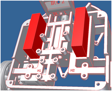
Battery packs
Two battery packs have to be built in. These are relatively heavy. This can be used to distribute the weight more evenly on the drive wheels. When the robot has to duel against another robot, this becomes a important feature.
 |
Indicative leds
Donĺt forget to use these. It is a very helpful tool to debug your software.
 |
On/Off switch
This doesnĺt take a lot of space but it has to be accessible.
Target selection
To select the opponentĺs goal location, on the black or white side of the playfield, a push button has to be accessible.
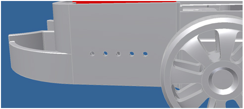
Caster wheel
This is used as a third wheel on the robot. On our design, this wheel is pretty large. When the position of this wheel is determined, consider a good weight distribution! [ top ]
 |
Feel free to download the following content:
- Inventor-files (RAR-file, 6092kB) [ top ]