Sensors and actuators
Pinpoint ball
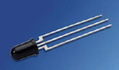
As the official ball of the Robocup games was given, it is obvious that we searched for an appropriate sensor to detect the ball, which radiates infrared light (IR). The ball has a narrow spectrum around a wavelength of 900nm. Therefore we chose IR sensors with specific sensitivity in that spectrum. The SFH 303 – FA was ideal because of this quality along with a 5V supply voltage, good output and relative linear path (this makes coding easier).
Measuring the grayscale
To measure the grayscale we used the same infrared sensor as is used to detect the ball on the field. This sensor, as mentioned before, has a high sensitivity around wavelengths of 900nm. Therefore we picked an infra-red source that emitted at this same wavelength. To be sure that any interference with the IR ball or other IR sources was minimized the emitter and receiver where directed to each other (at a distance of 4mm above the ground) and where enclosed with a hood (see also at the design of the robot). The sensor was put in series with a measuring resistor and a multi-turn potentiometer. This is necessary to reach an output voltage between 0V and 5V on the black and white side of the playfield. The potentiometer is used to adjust the output voltages because of the tolerance on the resistor values. There is a catch on this type of circuit. The resistor value on the gates of the analog input of the microcontroller must not be too high. This can lead to long A/D conversion time or causes problems with conversion of the analog input. The recommended maximum resistor value can to be found in the datasheet of the microcontroller.
|
Side-detection
To prevent the robot to hit the sides of the playfield, it is important to detect the side- and front wall. As the microcontroller program did not foresee any reverse movements a back view sensor was not necessary. The walls were detected, also, with an infrared detector, a Sharp GP2D12. The disadvantage of this sensor is the absence of linear response to the distance between the wall and the robot. To meet this non-linearity the sensors were placed in the centre of the robots frame (further explanation in the design topic).
Goal adjustment
The robot has to know on which side of the playfield his goal and thus the opponent’s goal is. With a simple push button the program receives a ‘high’ signal and adjusts his play-strategy (further explanation in the program topic).
Kick the ball
To kick the ball towards the goal a simple actuator is installed. This component has a required supply voltage of 12V. To actuate this solenoid a small transistor, which is controlled with the microcontroller (output of the microcontroller is 5V), is used to control a bigger transistor. This transistor is able to actuate the solenoid. To protect the circuit a diode is placed over the solenoid.