| PCB :: Downloads |
The main printed circuit board
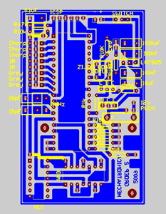
The microcontroller is the “heart” of this printed circuit board (PCB), so it is placed in the centre of the board. A common way to structure the board is to follow pins of the microcontroller, provide voltage from the centre and put the ground on the outside, surrounding all other elements on the PCB (as can be seen on our PCB). To start on the left side of the PCB and end on the right side, one can first see the components for the ‘In-circuit serial programming’ (as described in the course notes). On the left side of the microcontroller are all the analog signals of the sensors on the robot. We chose to make little PCB for the sensors so the main PCB would stay surveyable. These sensor PCB’s contains the components as mentioned in the explanation of the sensors. The separate boards were connected with simple three-pin-connectors. Below the analog connections is the electrical circuit for the clock signal. It is very important that this circuit is as close as possible to the microcontroller as possible to avoid interference on pulses of the clock. In the left lower corner and under the microcontroller is the logic the control the electrical motors. The H-bridges to actually control the speed of the engines are on separate boards. The logic to use the electrical motor both back- and forward contains a NOT- and a AND gate. This structure allows the control the sense of rotation with one output and one PWM signal of the microcontroller. From this side of the PCB, three pins runs to the separate PCB with the H-bridge (which is discussed below). In the upper right corner, right of the ICSP, we have the power supply and the main switch, which in our case is also used as a reset button. Beneath the power supply components is the push button for the goal adjustment and the electrical circuit to power the microcontroller (as described in the course notes). Beneath the power circuit are the transistors to actuate the solenoid to obtain the kick movement. Just below the transistors are the control LED’s, to see which routine is called in the program or to see if a problem appeared during operation. The control LED’s are actuated with the pins from the microcontroller who were still available.
H-bridge PCB
To keep the main PCB as little as possible the circuits of the H-bridges were separated from the main PCB. The components and their connections can be found in the datasheet of the H-bridge.
Remarks
Keep in mind that many components need a different hole diameter on the PCB and components dimensions are expressed in the Imperial Standard System not in the Metrical System. Remember to provide attachment holes so the PBD’s can be fixed to the frame. Example of these attachment holes can be seen in the pictures of our designs (the large holes on the PCB). [ top ]
|
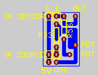
Figure: Sensor (Grayscale and IR) |
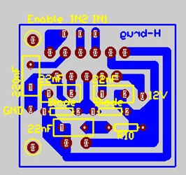
Figure: H-Bridge |
Figure: Complete PCB |
Feel free to download the following content:
- Complete PCB (pcb-file, 361kB)
- H-Bridge (pcb-file, 26kB)
- Sensor (pcb-file, 61kB) [ top ]