Our project doesn't require much electronic components, because we made our design pretty simple. If we would have chosen to use a gripping arm to grab the seeds instead of the container mechanism we use now, a lot more feedback would be required to check if the sowing was successful.
Electronic components:
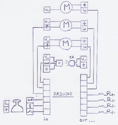
The first components we need to control are the two servo motors that move the robot arm and the servo motor that plants the seeds. All three of them will be powered by a lab power supply and the control signal will be provided by the arduino. We decided to read out the internal potentiometer of the two servomotors (that take care of the positioning of the arm) with the arduino to get some feedback.
To make sure if a seed was planted, an infrared led and detector were mounted on our sowing head. They are both powered by the lab power supply and the arduino reads out if a seed has went down the sowing head or not.
We also wanted to add the option to manually plant seeds in any desired location without the use of the computer program provided with the robot. To accomplish such a thing, we added a joystick to our set-up. The joystick consists of two potentiometers and a button, which are connected to the arduino.
To see if the servo motors were in their desired position or not and to see if the arduino was busy receiving information from the computer or not, some led's were added. This led's are powered and controlled by the arduino as well.
Finally, a switch was added to provide power to all the electronics on our PCB unit.
The final circuit for our electronics looks like this:
Construction of the PCB:
Once all the necessary electronic components have been identified and all control software for the arduino were written and tested, it is time to build a PCB to mount on our arduino.
We held some rules into account while designing our PCB in "traxmaker":
- Don't make paths intersect in the design of your PCB
- Design your PCB so the different components can easily be detached by using connectors
- Increase the width of your paths if you know more current will flow through them
- To speed up the construction of the PCB, only cut out the least amount of copper needed on the baseplate for the PCB, and for extra safety connect this copper to the ground of your circuit board.
- Try and make the PCB as compact as possible
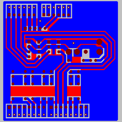
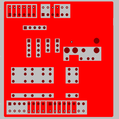
All these rules were taken into account, and we chose to build a double sided PCB to be able to solder all the led's on the top of the PCB while making a connection to the arduino on the bottom of the PCB.
The final design of the PCB looks like this:
And can be downloaded here:
Right click to download traxmaker file here