The mechanical portion of this assignment can be easily divided into the design and assembly of two major portions of the robot: The robot arm that will take care of the accurate positioning of the sowing head and the sowing head itself.
The robot arm:
Our first brainstorming session was about which type of robot arm to use. The following possibilities came up along with a vehicle type robot:

We chose to use a SCARA type robot arm, despite of the fact a linear moving arm would be easier to program. The linear robot has the problem that it is harder to check a linear movement with a sensor for feedback. We also wanted some challenge in controlling the arm. And let's face it, it looks way better than a crane type robot hanging above our set-up.
The movement will be provided by with servo motors, these are easy to control and easy to adapt to gain feedback on the positioning (we adapted them so we could read out the value of the internal potentiometers. The only downside is the range of 180° of the servo, but in our assignment we could reach our entire planting ground with two servos and an appropriate length for the arms.
In the actual build of the arm, we used our biggest servo engine as the fixed point to which the arm was connected to the ground plate. The small servo was placed on top of the first arm piece.
The design of our robot arm eventually resulted in the following 3D-model.
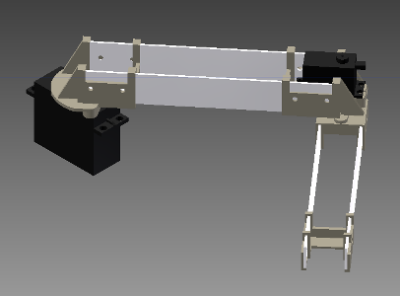
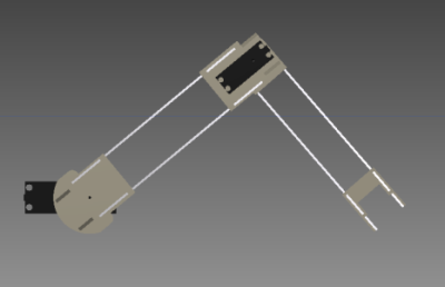
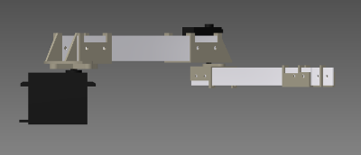
Notice we made large parts of the arm in aluminum to reduce weight, improve strength and save printing material.
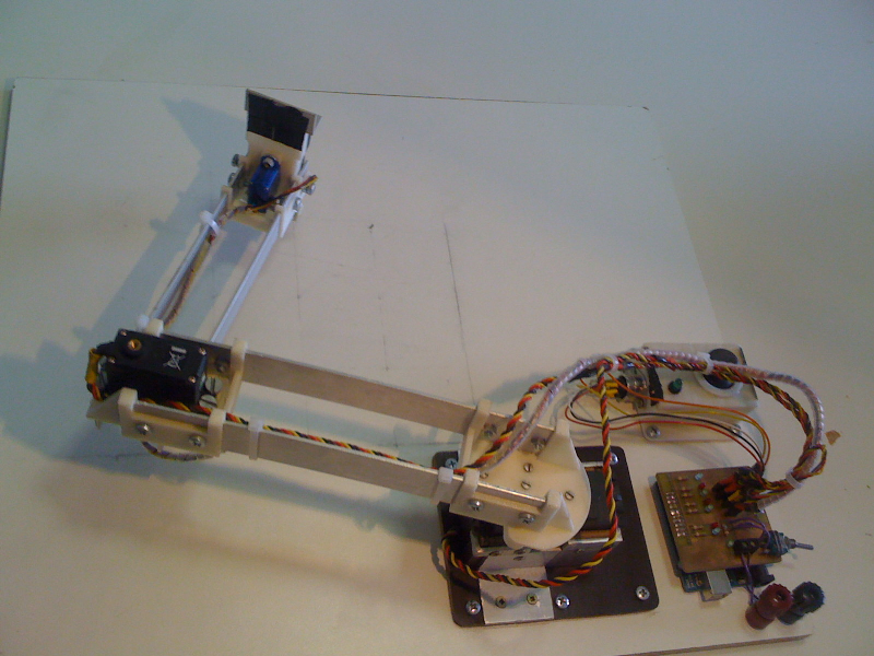
Here are some pictures of the completed robot arm:
The sowing head:
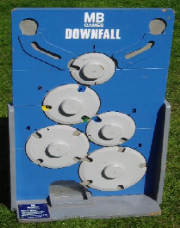
To be able to plant the seeds, we immediately decided we were going to work with a system where we would keep the seeds in a container on top of the sowing head, instead of grabbing the seeds from somewhere. The only remaining problem was to subtract one seed at a time from our container. To solve this problem, we used a method found in the popular game "Down Fall".
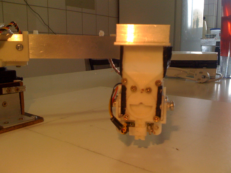
The sowing head consists of the support part, one mini servo motor to turn the wheel that transports the seed in the sowing head support part and the wheel. The entire sowing head will be covered with a plastic cover, so you are able to watch the seed as it gets planted.
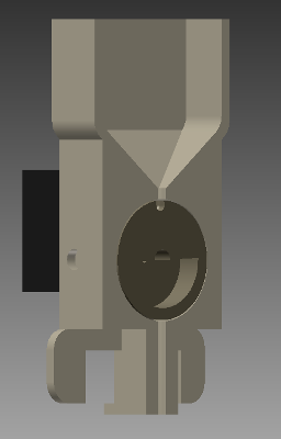
Here is a picture of the completed sowing head:
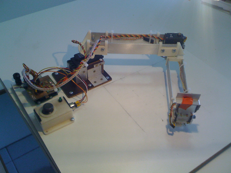
And here is a picture of the complete sowing robot:
The file containing all our inventor files can be downloaded here:
Right click to download inventor files here
The positioning of the arm:
The positioning of the robot arm happens is controlled by two angles, θ and φ. The computer program however, uses Cartesian x, y coordinates so a conversion needs to be provided. This conversion happens like this:
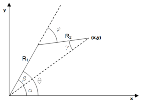
α can be calculated directly from the x- and y-coordinates:
α=atan(y/x)
If R1 and R2 are projected on the dotted line between the origin and (x, y), we can find:
R1 cos(β)+R2 cos(γ)=x/cos(α)
The arm has one degree of freedom left when choosing the x- and y-coordinates. This one is fixed by applying an artificial connection in which we state that:
R1 cos(β)=R2 cos(γ)
This way, β and γ can be calculated:
β=acos(x/(2R1 cos(α)))
γ=R1/R2 cos(β)
Using these angles, θ and φ can be calculated to make sure the robot arm is positioned at the correct x- and y-coordinate:
θ= α+β
φ= β+γ