Electric design
Electronic circuit
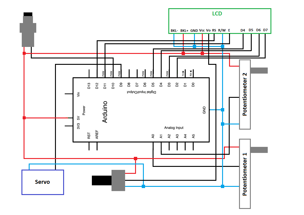
In the picture below you can see a scheme of the electronic circuit.
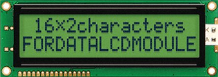
LCD Screen
The LCD screen we used is from the manufacturer Fordata
and the product name is "LCD, alphanumeric 16x2, STN, reflective".
A picture of the LCD screen is shown below the table with specifications.
Parameter |
Value |
Unit |
External Dimensions H-W-D |
122 x 44 x 9,5 |
mm |
Fixing Hole Diameter |
3,5 |
mm |
Number Of Characters - Lines |
16 x 2 |
|
Display Type |
Reflective STN |
|
Colour |
Yellow-Green |
|
Function
The function of the LCD screen is to provide interaction with the user.
It is used to set the force level, ranging from 1 to 10, and to set the number of squeezes, ranging from 1 to 50.
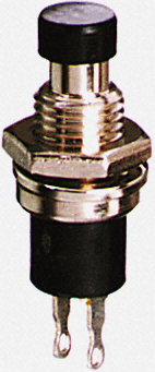
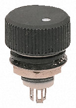
Pushbutton
One pushbutton is used to enter the asked force level and the selected number of squeezes.
The manufacturer is Knitter-switch.
You can find the pushbutton under the name "SPNO black panel mount pushbutton switch" on the site of RS components.
Specification |
Value |
Unit |
Contact Rating |
100 mA @ 30V dc |
|
Contact Resistance |
20 |
mOhm |
Panel Cut Out |
7 |
mm |
Functioning
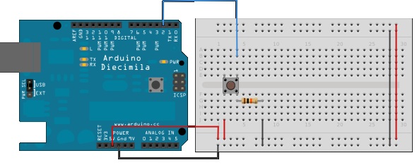
The connection of the Pushbutton with the Arduino bord is realised by the circuit shown in the figure below.
Pushbuttons or switches connect two points in a circuit when you press them.
When the pushbutton is open (unpressed) there is no connection between the two legs of the pushbutton,
so the pin is connected to ground (through the pull-down resistor) and reads as LOW, or 0.
When the button is closed (pressed), it makes a connection between its two legs, connecting the pin to 5 volts, so that the pin reads as HIGH, or 1.
An in detail explanaiton can be found on the
Arduino website
.
Potentiometer
Two rotating potentiometers were necessary: one to choose the force level and another to change the brightness of the LCD screen.
We selected the "P16 1 turn Cermet Knob Pot,10K lin 16mm" from manufacturer Vishay.
Specification |
Value |
Unit |
Number of turns |
1 |
|
Power rating |
1 |
W |
Diameter |
16 |
mm |
Height |
24 |
mm |
Resistance value |
10 |
kOhm |
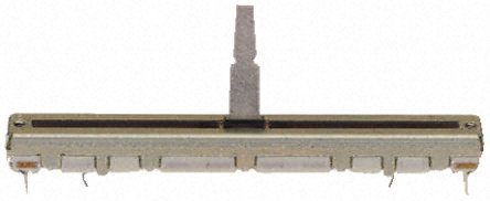
Linear potentiometer 1
To detect the position of the moving handle, a linear potentiometer was used.
The name of the product is "Std slim line slide pot" and it is produced by ALPS.
Specification |
Value |
Unit |
Length |
6 |
cm |
Power rating |
0,2 |
W |
Resistance value |
50 |
kOhm |
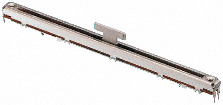
Linear potentiometer 2
To determine the zero position of the spring we also used a linear potentiometer.
The name of the product is "Super slim line slider pot" and it is also produced by ALPS.
Specification |
Value |
Unit |
Length |
10 |
cm |
Power rating |
0,5 |
W |
Resistance value |
10 |
kOhm |
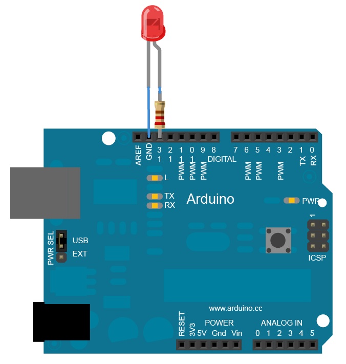
LED
Also Light Emitting Diode (LED) was used to interact with the user.
The LED lights up when the spring is fully streched.
The connection was made as shown in the figure below.
To build the circuit, a 220-ohm resistor was attached to pin 13. The long leg of the LED (the positive leg) is connected to the resistor.
The short leg (the negative leg) is attached to the ground.
An in detail explanation of the programming is found on
this link
.
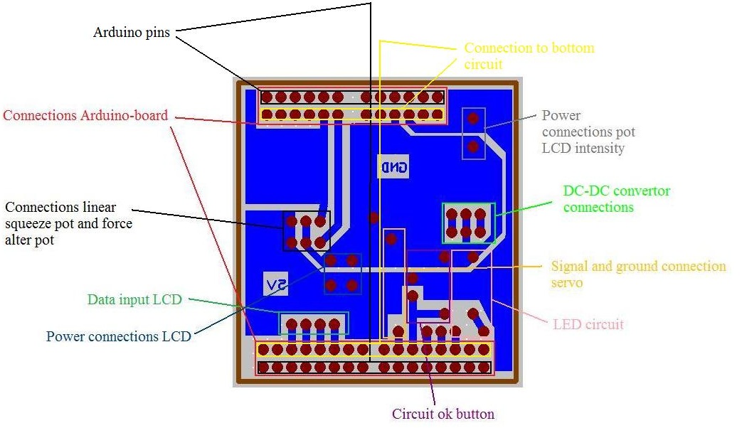
Printed circuit board
The electronic circuit was built on a PCB. The PCB was designed by us in a program called Traxmaker.
The design is shown below. Only the bottom layer is displayed.
The top layer was only used to connect the Arduino pins soldered at the top with the circuit at the bottom.