Mechanical design
Basic design
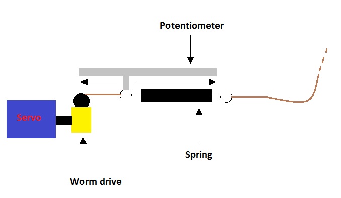
The basic concepts of our design are quite fundamental and straight forward: a spring will replace the rubber bands.
By changing the elongation of the spring by means of a servomotor we can adjust the resistance, resulting in different training levels.
The ends of the spring will be connected to two cords: one of them is connected to the lower bar of the device,
the other to an axis which is driven by the servomotor.
If more force is requested, the servomotor will wind up the cord thus elongating the spring.
The axis of the servomotor and the axis of the pulley for the cord are mechanically connected by a worm drive.
By doing this the motor does not have to keep supplying torque. It only needs to operate when change of the force level is requested.
The zero position of the spring and the position of the moving bar will be measured by using two linear potentiometers.
Sizing of the components
At the minimum force level the resistant force should almost be zero at the beginning of pulling.
The maximum force was estimated to change from 10N at the beginning of pulling to a little under 20N when the handles touch each other.
Taken in account that the handles should change over a distance of 5cm for an average hand,
we can calculate the spring constant.
After selection of the worm drive and pulley we can determine the necessary torque.
The data is summarised in the table below.
Parameter |
Value |
Unit |
Max. force possible when the hand is open |
10 |
N |
Max. force possible when the hand is closed |
17 |
N |
Max. distance between the two bars (hand open to closed) |
5 |
cm |
Spring constant |
131,5 |
N/m |
Gear ratio of worm drive |
20 |
|
Diameter of the pulley were the cord is wind up |
2 |
cm |
Max. needed couple of the motor |
0,085 |
kg.cm |
Component Selection
The spring
The spring was ordered at Alcomex.
However as a result of some problems between the company and the university the springs were not yet delivered at the time of our deadline.
As a last resort we used a spring from the lab.
Unfortunately we do not know the exact parameters of the spring and all parameters of the design are chosen based on the Alcomex spring.
The Alcomex spring's spring constant is about half of what we intended to use. This means that, when pretensioning the spring,
the spring needs to be stretched further than the distance we initially designed for (7cm).
As a result, our current device does not provide the resistance we intended it to at its maximum force level.
The servomotor
|
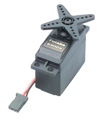
The manufacturer of the motor we selected is Futaba.
The manufacturer number is S3003. This servo can draw a relatively large current from its power supply.
We have to make sure the power supply is capable of delivering sufficient amps. Relevant specifications are summarized in the table below.
The servo can only turn over an angle of 180 degrees.
A mechanical stop prevents the servo from rotating any further. This is insufficient for our application thus the mechanical stop needs to be removed.
The position of the servo is controlled by a rotational potentiometer, which can also only measure 180 degrees.
We thus need to replace this potentiometer as well. The servo is used to set the displacement of a spring, which is a linear movement.
This can easily be measured by a linear potentiometer, which we connect to the servo instead of the rotational one.
The potentiometer will now rotate until the lever is in the correct position, allowing for an easy control of the spring displacement ergo spring tension. |
 |
Specification |
Value |
Unit |
Torque |
3,2 |
kg.cm |
Speed |
0,23 |
sec/60° |
Voltage |
4,8 |
V |
Dimensions |
40 x 20 x 36 |
mm |
Weight |
37 |
g |
Power supply
|
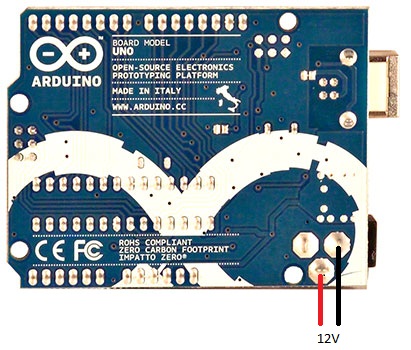
The Arduino board is powered by a simple adapter (AC/DC converter) at 12V DC.
The servo can operate on a voltage of 5V, meaning that the 5V output of the Arduino can be used to power the servo.
However, a servo can draw considerable amounts of current. It is therefore wiser to connect it to an external power supply.
We already have the 12V coming from the adapter, which can easily be subtracted from the Arduino board by soldering two wires to the pins shown in the figure on the right.
Unfortunately, 12V is too much for the servo. It is therefore converted to a 5V DC voltage by a DC/DC converter on the PCB. |
 |
The worm drive
|
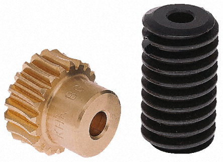
The pinion and worm gear are from the manufacturer RS-components.
Specifications are given in the table below.
Unlike with ordinary gear trains, the direction of transmission (input shaft vs output shaft) is not reversible.
This can be an advantage when it is desired to eliminate any possibility of the output driving the input.
We use this in our advantage because in this way the motor does not have to deliver a torque during the squeezes, but only when the force level is changed.
This decreases energy consumption. |
 |
Specification |
Value |
Unit |
Material pinion gear |
Bronze |
|
Material worm gear |
Steel, Bronze |
|
Module |
0,8 |
|
Number of teeth pinion gear |
20 |
|
Overall diameter pinion gear |
17,6 |
mm |
Overall diameter worm gear |
15,6 |
mm |
Pitch diameter pinion gear |
16,03 |
mm |
Pitch diameter worm gear |
14 |
mm |
The cord
The two cords are made of Kevlar.