Electronics
As control system we chose to use a microcontroller integrated in an arduino uno board because of its easy use.The other components in our circuit are the LCD display the electronic circuit and the sensors.
Sensors:
To measure the velocity, we use a reed sensor from a normal bike computer.The sensor is debounced with a low pass filter.
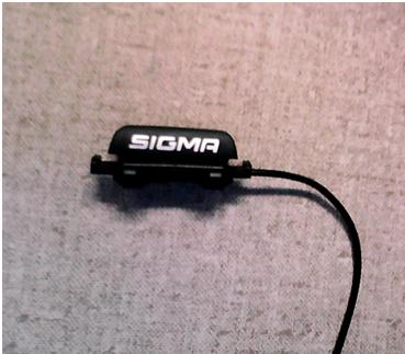
Reed sensor
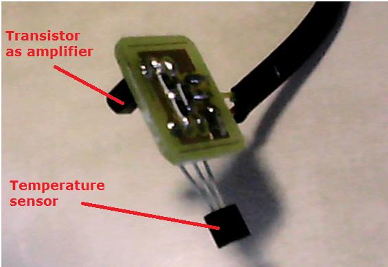
The temperature is measured with a TMP36.
This is a linearized thermistor that does not need any calibration.
It allows us to measure the battery temperature up to 125°C with an accuracy of 2°C.
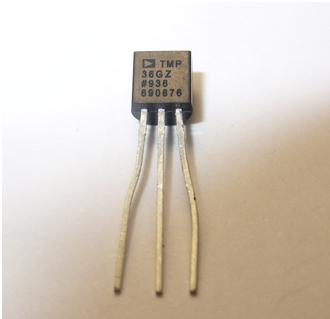
Temperature sensor
We also used a standard linearized current sensor with which we can measure the motor current up to 20A.
PCB's
Component assembly
In order to protect the electronic parts and for simplicity, the display, the arduino and almost the whole circuit are placed together.The sensor and the processing and amplification of their signal are best placed together to minimize noise.
For instance, if the signal is not amplified before the signal is sent to the arduino the signal-noise ratio is smaller and the effect of noise on the system is larger.
The part with the arduino, main circuit and display is originally three levels high.
Moreover the arduino is larger than the display and not the whole arduino circuit is used.
In order to minimize the size of this part of the circuit we decided to combine the needed part of the arduino and the main circuit together on one circuit board.
The dimensions of this board are the same as the display.
The whole circuit to communicate with the USB is removed and only two pins for the upload of programs to the microcontroller are placed on the new board.
To upload a program on this new board these two serial communication pins have to be connected to the same pins of the arduino.
Network
The central part of the network is the display-microcontroller board.A wire bundle connects the central part with the current sensor board from which the voltage and temperature wires are connected to their respective sensors.
This is possible because these physical quantities are measured near each other in the Ecocar.
Two other wires are directly connected to the velocity hall sensor at the wheels.
EAGLE
To design the printed circuit boards the program EAGLE is used.Most of the components were already in the libraries but some specific ones had to be added.
The difficult and time consuming part was to choose the right components out of lists of possibilities.
For example resistors exist in multiple different packages and the best suited were finally large SMD packages with code 1206 and 805.
Once all these components were linked to each other on their respective boards the second part of the design began.
The second part is the design of the physical connection between the elements on the PCB using the top and bottom layer.
In order simplify the network the components have to be rearranged.
To do so the number of connections between the layers has to be minimized as well as the length of the wires.
Also the grounds have to be connected; the pins have to be positioned at the borders; the thickness of the wiring for power is larger than the ones for signals.
Photos of the EAGLE documents
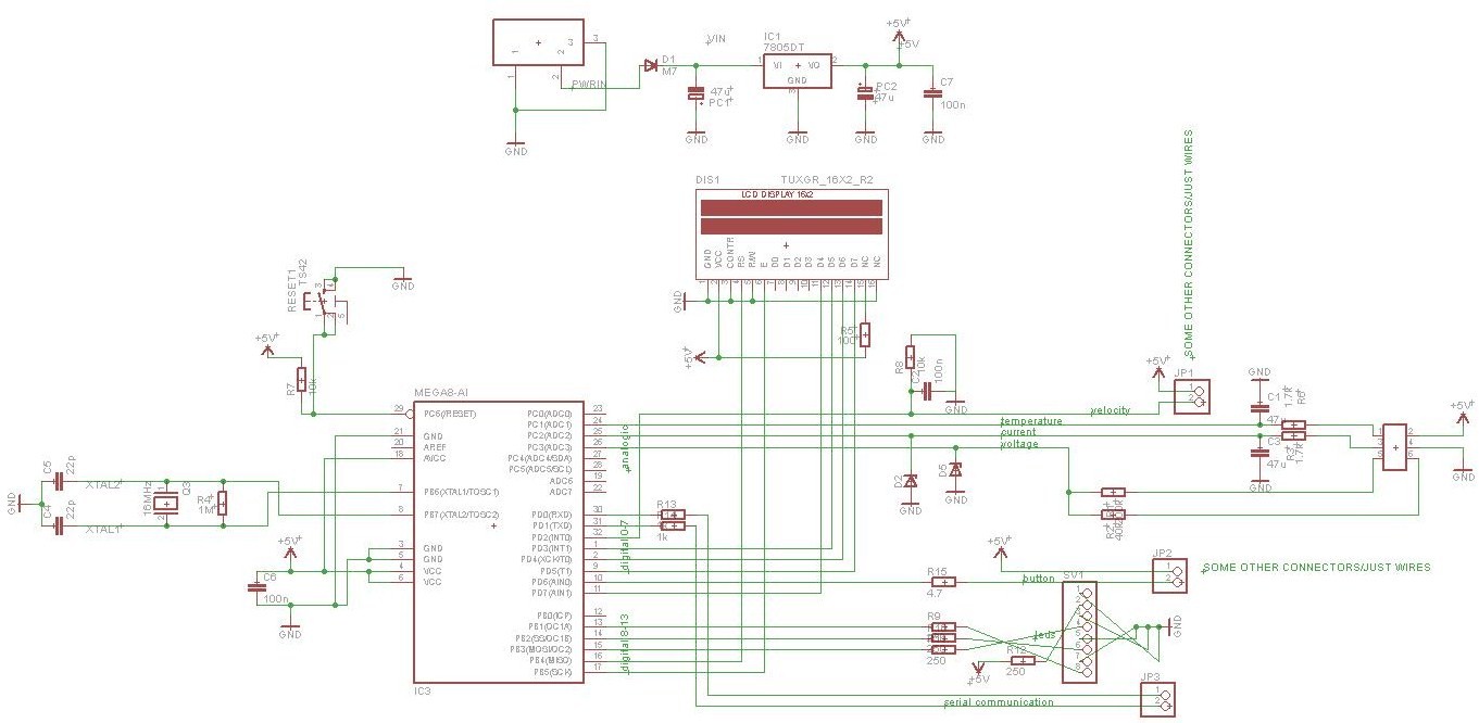
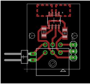
scheme in EAGLE of the PCB with the arduino
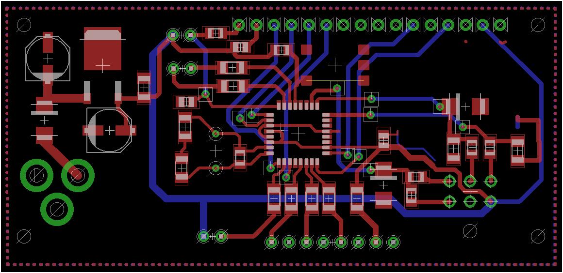
board in EAGLE of the PCB with the arduino

on the left: scheme in EAGLE of the PCB with the current
on the right: board in EAGLE of the PCB with the current

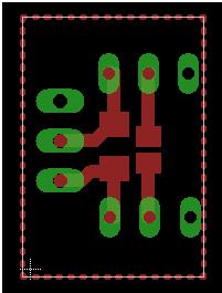
on the left: scheme in EAGLE of the PCB with the temperature
on the right: board in EAGLE of the PCB with the temperature
Photos of the finished PCB's

on the left: pcb for the current sensor
on the right: pcb for the temperature sensor
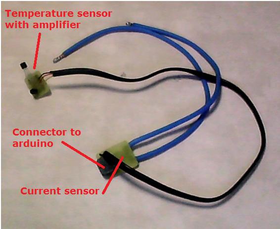
pcb with the temperature sensor connected to the pcb with the current sensor

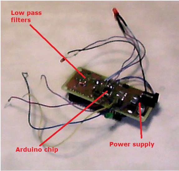
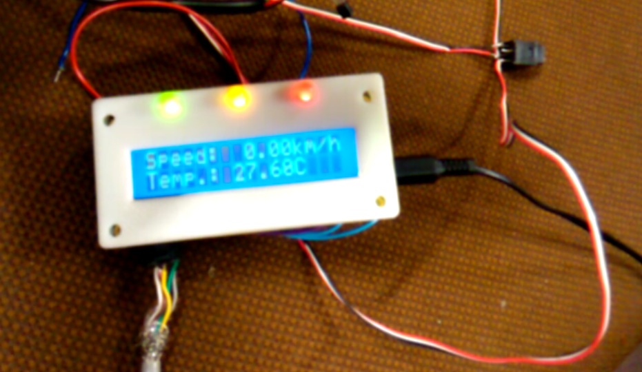
on the left: Side of the display on the arduino
on the right: backside of the arduino with the low pass filter, the arduino chip and the power supply
Final project