In this Whegs project, the Arduino microcontroller and software will be used.
A short introduction to the different steps undertaken to get acquainted with the Arduino
will be explained on this page. Also it will be shown how to implement the Atmega328 microcontroller
on a breadboard, without the use of the Arduino Uno PCB. Gradually, the evolution towards the PCB
design, necessary to control the entire robot, will be explained on this page. This information, and
so much more, can be found on the
Arduino website.
Step 1: What is ‘an Arduino’?
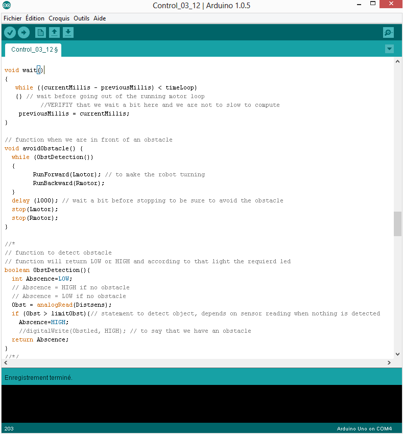
Arduino Code (Click to enlarge) |
Arduino stands for open source microcontroller soft- and hardware. The software is
Arduino IDE and allows the user to program the microcontroller in a C-kind language.
It can also be used to upload the software that was encoded to the microchip. All you need
to know about this can be read on this
Getting Started Page.
Arduino PCB’s come in different types, with different sizes and possibilities. The most basic PCB,
is called the
Arduino Uno. This will be the Arduino board that will be used to start this project.
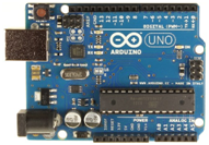
Arduino 1 |
Once an Arduino board is available, the first task will be to learn to know how to supply
the PCB of the correct voltage. The Arduino Uno can be supplied using just the USB cable to
connect it to a computer, or an external voltage source (7-20 V) can be attached to the source
plug. Once this is done, the focus can shift towards the real use of the Arduino. On the board,
different connection pins are available. A thorough explanation of the pins can be found here.
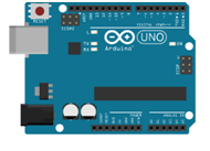
Arduino 2 |
Necessary to know is that there are 4 categories of pins: voltage supply pins (3.3V or 5V),
Analog input pins,
Digital i/o pins and Digital i/o pins with PWM capability. On the previous
these pins are shown respectively in the green, red, yellow and blue rectangle. It is also
important to know the restrictions of these pins. The 5V, 3.3V Digital i/o and PWM pins can
deliver a maximum of 5 V (except the 3.3V pin obviously) and 40 mA.
Step 2: First test
To gain some experience on working with the Arduino, a small test is performed.
The objective will be to blink the Led that is connected to pin number 13 on the Arduino
board. In order to achieve this target, the following code is uploaded to the Arduino.
Code
Step 3: Robot control
a. Objectives:
The idea is that the robot will exert a certain motion that is ordered until
the stop button is pressed, or an obstacle is detected (only in the forward motion).
The controller has to determine whether there is an obstacle the robot cannot overcome or
not in front of the robot (using Infrared Sharp Sensor). The motion of the robot is determined
by reading the Infrared signal coming from the remote control (using Infrared receiver).
b. Flow chart:
A flow chart is used to represent the functioning of the robot

Flowchart Arduino code |
Flowchart Arduino code |
c. Function explanations:
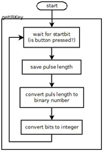
- getIRKey(): function that detects the signal coming from the remote
control and transforms this to an integer value. The following flowchart shows how
this function will operate.
It is important to notice that we are using a specific SONY protocol (SONY remote that was available).
This infra-red protocol transmits information based on the time that elapses between pulses of the same
amplitude. The signal itself is 12 bits (pulses) long, extended with one starting bit. Threshold values
for the time that passes between two bits, are used to transform the measurement to a binary number. This
means that it is only necessary to determine the time between two pulses, and not the height of the
pulses. The pulseIn() function is perfectly suited for this purpose.
Remote control signals |
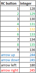
In order to be able to perform the motion determination based on the value of the integer, returned
by the getIRKey() function, first the corresponding integer value for different buttons has to be
identified. This can be done by connecting the infra-red receiver to a digital input pin of an Arduino
and uploading directly the getIRKey() function. Using the serial communication, the integer values for
different buttons can be read. The result of this identification is shown in the next table.
Remark: notice that a bug is present in the code
or in the remote control. Both the arrow up and the arrow right button
give the same integer number. It is true that the remote control is old and
actually no longer used, since some buttons weren’t functioning any more. Nevertheless,
enough buttons gave a good integer reading to use this remote control. The test of the
remote control, using the motion indicator LEDs and a speed indication led, can be seen on the
following video. In the video, the Arduino board is replaced by the Atmega chip on a breadboard.
The explanation on this setup can be found later on this page. More information on the infra-red
receiver can be found on the page covering the sensors.
Before the decision was made to use a tv remote control, the idea was
to make the remote control for the robot exploiting the possibilities of using Arduino shields.
The XBee shield allows wifi communication. Disadvantages of this approach were that two XBee shields
were necessary (quite expensive) and the remote control had to be designed in addition to the robot.
- ObstDetection(): checks if an obstacle is detected in front of the robot. Therefore it has to use the readings coming from the infrared sensor.
- Determination of motion
The robot determines what motion it has to perform based on the signal coming from the getIRKey() function. A case statement can be used to check this.
- The motion functions include the motor controlling functions and the lightning of the LEDs to show what motion is being performed by the robot.
- If the stop button is pressed, the robot will stop the motion it was exerting on that time. To show this, the leds will first go low, blink once and return to the low state. Now it is possible to give the robot a new assignment.
Now, this concept has to be translated into code. The result is written in the "Programming" section.
Back to Top


 The Whegs-Robot Team
