Communication with the Robot
The IR sensor |
Because the goal is to have a robot, controlled by a user, communication with the robot
should be designed. A long wire is not practical and could cause a lot of noise in the signal.
A remote control is therefore a better solution. Here, an IR sensor is used which makes
communication through infra-red waves possible.
Obstacle Detection
The position of the Proximity Sensor |
Although the robot is specially made to overcome obstacles, there are still a lot of obstacles
it cannot overcome. The maximal height of an obstacle that the robot can overcome is given by
1.75 times the radius of the Whegs. Thus the robot needs a sensor to detect these obstacles.
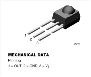
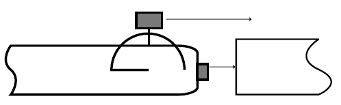
This is why an obstacle detector (sharp sensor GP2Y0A21YK0F) is used. This sensor will be put on top of the
robot (as shown on the figure) and then if an obstacle is bigger than the height of the robot, the robot will stop and send
a message (by led) to say that the obstacle is too high. The position of the sensor ensures that
all the impassable obstacles will be detected.

The sharp sensor |
The range of this sensor is from 10 to 80 cm. The robot will be able to detect obstacles in this
range of distances. The output of this sensor is analogue; it will be therefore connected to an
analogue input of the chip. As this sensor needs about 5V as supply voltage, it will also be
connected to the 5V and the ground pin of the PCB.
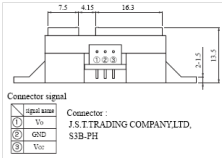
The sharp sensor pins |
The three pins of the sensors are described in the figure at right. The three pin are the
output of the sensor (Vo), the connection to the ground (GND) and the connection to the supply
voltage (Vcc). These pins have to be well connected in order to get measurements and to not
damage the sensor.
No precise information is given in the datasheet of this sensor about the output signal.
Tests were performed in order to characterize the output of this sensor. The code below was
used (
link to the code):
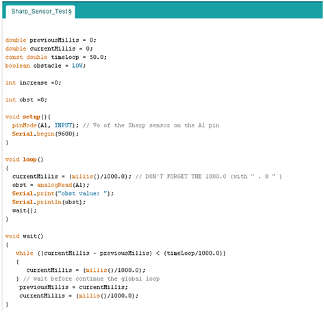
Arduino Code (Click to enlarge) |
The goal of this code is to print the values given by the sensor every 50 ms. The test
that took place was the following: using a black plate modelling the obstacle, one gets
the results given by the sensor for different distances between the IR sensor and the plate.
The values measured were going from 20 to 600. A high value corresponds to a small distance
(obstacle close to the sensor), and vice versa. Some oscillation were observed. Indeed, even
if the plate was not moved, the data given by the sensor were oscillating around an average value.
To use this sensor, it could be good to average the values measured during a small amount of time
to get the average value, closer to the real measurement corresponding.
Another test was to switch on a LED when the value measured was higher than a threshold
(300 in this test).
Rotation Control (use of Encoder)
The servomotors that are used to actuate the robot were hacked to turn infinitely. So the position
control they contained has disappeared. The only thing which can be controlled by the servomotors
is the velocity of the actuation. But for the robot control, a feedback on the rotation of the
Whegs is needed. Thus an encoder is required to record the position of the Whegs. This is why two
encoders are used. Only two encoders are needed because the Whegs on each side are connected by
the belt.
In the Arduino Servo library, a function can be used to impose the rotation in the case of a
limited servo motor (non-hacked), or the speed for a continuous rotation servomotor (our case).

Quadrature Output Table |
A control on the angular position of the motors is really important. Indeed, the two motors,
even if they are built by the same manufacturer, can have slight differences. If a certain value
is given for a rotation speed, the two motors can react differently. This can cause a rotation of
the robot when it should go in a straight line. To avoid this phenomenon, it is possible to control
the speed of the motor. As described in the “Programming” section, a proportional control was written
to avoid this behaviour. A reference is imposed by the user with the remote control. The motors
have to achieve this rotation speed. If one motor turns too slowly, another value will be given
to the special function of the Arduino library. This new value will be proportional to the error
between the reference and the actual angular position of the motor. To know this position, an
encoder is used. The encoders used have two digital outputs. As shown in the picture, the output
A and B give a kind of square wave signal in quadrature of phases. This difference of phase will
allow the robot to know the direction of rotation (clockwise or counter clockwise).
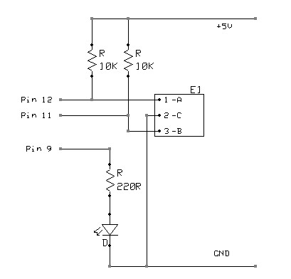
|
The scheme shown in the figure at the left hand side was used to perform the tests on the encoder.
The outputs need to be connected to the 5V pin by a resistor link. The third pin of the encoder
is connected to the ground. The Arduino Uno was firstly used to understand the behaviour of the
encoder. A simple test was performed in order to know the values given by the encoders. A code
found on the same website was tried, and was successful (see below).
In order to know the number of pulses per rotation, a simple program was written. Each time a
change occurred in the condition on output A or B of the encoder, a counter was increased.
By doing a rotation on the encoder manually, 16 pulses per rotation were counted. Through this
characteristic, the angle measured by the encoder for each pulse is known. Since there are 16
pulses for 360°, this means that each pulse corresponds to 22.5° (=0.4 rad). As the radius of the
wheels is about 7cm (=0.07m), this means that each pulse corresponds to a distance of
0.07*0.4=0.028m. This value will be used in order to compare the measured value and the reference
to achieve.
As the maximal rotation speed that the robot could achieve is around 1 rotation per second,
for 16 pulses per rotation, this means that at maximal speed, the pulses will be separate by
62.5ms. By using a sampling time (a period of loop) of 50ms as in the other loops, information
will be lost. The code shown below is simple to understand. Every time loop (here chosen as 5ms,
in our code around 50ms), the outputs of the sensor is recorded. Then, the last value of the
output A is studied, if the output is going from HIGH to LOW, this means a change took place and
if the other output is HIGH, this means that the rotation is Clockwise. If these conditions are
fulfilled, the desired action can be executes. If the rotation is counter clockwise, the value
should decrease, because the rotation is going in the other direction.
Back to Top

)
)
 The Whegs-Robot Team