Design Bridge robot
Mechanical parts
Wheels
There are two driving "k'nex" wheels for the motion of the robot and
a castor wheel for the support. It was easier to use the "k'nex" wheels because we already had them, so there was no need
to print or buy different ones. However, an adaptor had to be created to fix them to the motors. Two models of adaptator was created
and finally, it was the white one (see on the picture) which was chosen. Regarding the castor wheel,
it was bought in a shop. It had to be raised because otherwise the robot would be leant to the front (see on the picture).


Support for the PCB and the Arduino
The PCB-Arduino block is placed above
the castor wheel. Indeed, there is a laser cut bridge where both the PCB and the Arduino can be put on.
This bridge is also the place where the castor wheel is fixed, allowing to raise it.

Arm and gripper
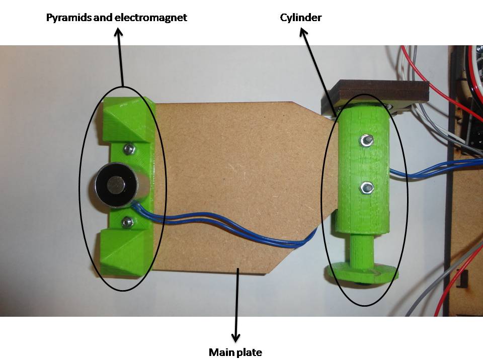
The arm is composed of three parts: the support of the pyramids, the cylinder and the main plate.
The first one is composed of two pyramids and an electromagnet in between them. Indeed, for the gripping task,
rather than using a classic gripper (like a clamp) to take the bridge, it was decided to put a little metal part in the bridge
so it can be gripped with an electromagnet. The use of an electromagnet was an easy solution to lift the arm because then the robot
only needs one motor to move the arm.. To avoid that the bridge slips or turns when it is attached to the arm, two pyramids
were printed in order to fix the bridge in the right place. These pyramids go in square holes made on the bridge.
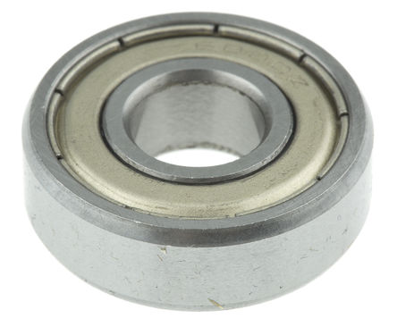
The second part is the cylinder, which is the base of the arm. It is a printed piece and it is the connection
between the arm and the motor. Also, since the width of the arm is long and its weight is high (as it must carry the bridge),
the cylinder need to be supported by a bearing on the other side.
The principal plate allows to link the electromagnet
to the cylinder (and also to the motor). Its length is 128mm and it was also laser cut.
Support of the distance sensors
As the distance sensor measured only from 10 cm to 80 cm, they had to be raised of 10 cm of the floor. That is why a support for the
distance sensors longed of at least 10 cm had to be laser cut.

Bridge
The bridge is composed of two plates: a bigger one with two color lines
at the two end tips and a smaller one which is glued on the first one. They both have a thickness of 4 mm and two square holes
where the pyramids of the arm are placed. Moreover, the little part has a circular hole where the metal part for the electromagnet
goes. These two parts were laser cut.

Assembly of the robot
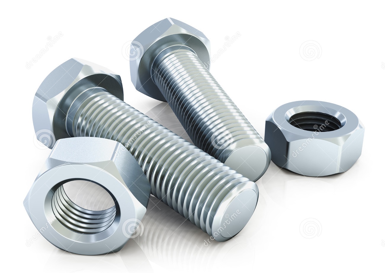
After having commanded, cut, printed and received
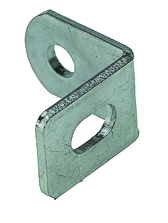
all the components necessary for the robot, the assembly could start. For that, the principal used tools are bolts and nuts.
Brackets are used to reinforce some structure parts and to attach them easily. There are also some parts of the bridge that are
glued.
Electronic components
| Part | Quantity | Function | |
|---|---|---|---|
| GP2Y0A21YK0F Infrared sensor | 2 | Distance measuring for gap detection and alignment |  |
| TCS3200 Color sensor | 2 | Correct positioning between the robot and the bridge |  |
| TIP120 transistor | 1 | Control the flow of a high-current circuit from a low-current source |  |
| 10k resistor | 1 | Control the output current from the arduino |  |
| 1N4007 diode | 2 | Protection of other components from back voltage |  |
| Futaba S3003 servomotor | 1 | Move the robot arm |  |
| Parallax servomotor | 2 | Move the robot wheels |  |
| Arduino UNO | 1 | Control the system |  |
| 1.5V AA battery | 8 | Power the system |  |
| 4-Battery holder | 2 | Hold the batteries and provide a 6V power |  |
| Printed Circuit Board | 1 | Mechanical support and electrical connection of the electronic components |  |
PCB
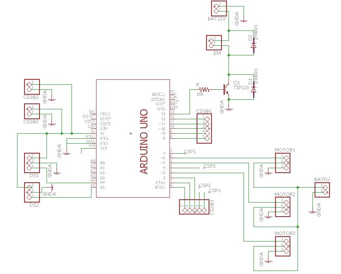
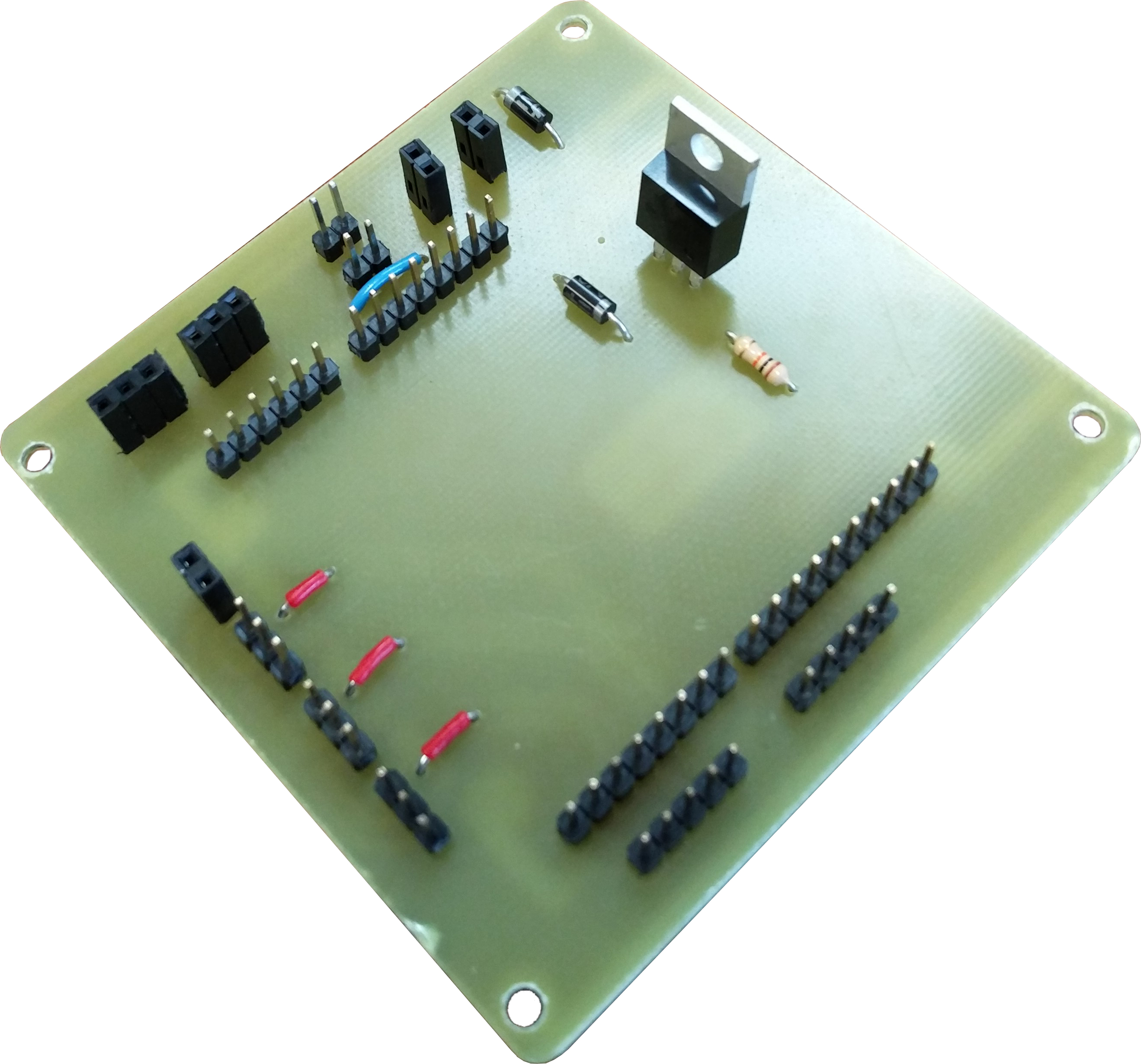
A Printed Circuit Board was made for the electronic components of the robot. The picture below shows the schematic of the circuit, where different parts can be found, such as:
- Electromagnet (EM) It is powered with 12V (taken from both battery holders) and there is a transistor that allows the control of the magnet from the small current of the output pin of the Arduino and a couple diodes to protect from back voltage.
- Motors They are powered with 6V (from just one battery holder) and they are directly connected to the PWM pins of Arduino.
- Distance sensors (DS) They are powered with the 5V pin from Arduino and they are directly connected to the digital pins of Arduino.
- Color sensors (CS) They are powered with the 5V pin from Arduino and they are directly connected to the analog pins of Arduino.The connectors for the outputs of the sensors are separated from the connectors of the power and ground to have a more clear schematic.
All these components are now placed in the board. They are placed in a way that minimize the lenght of the connections. It has been also designed to be a 1-layer PCB, but the use of jumpers was needed in some connections. The board also has 3.2 mm holes in the corners for letting the screws go through.
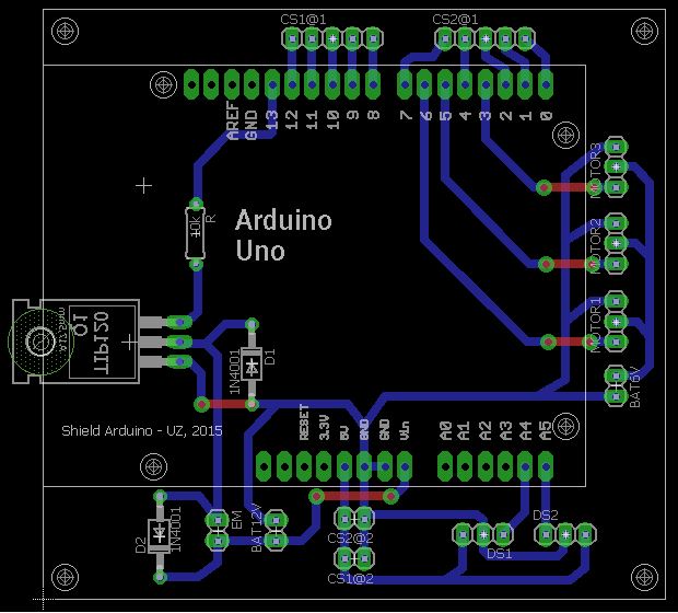
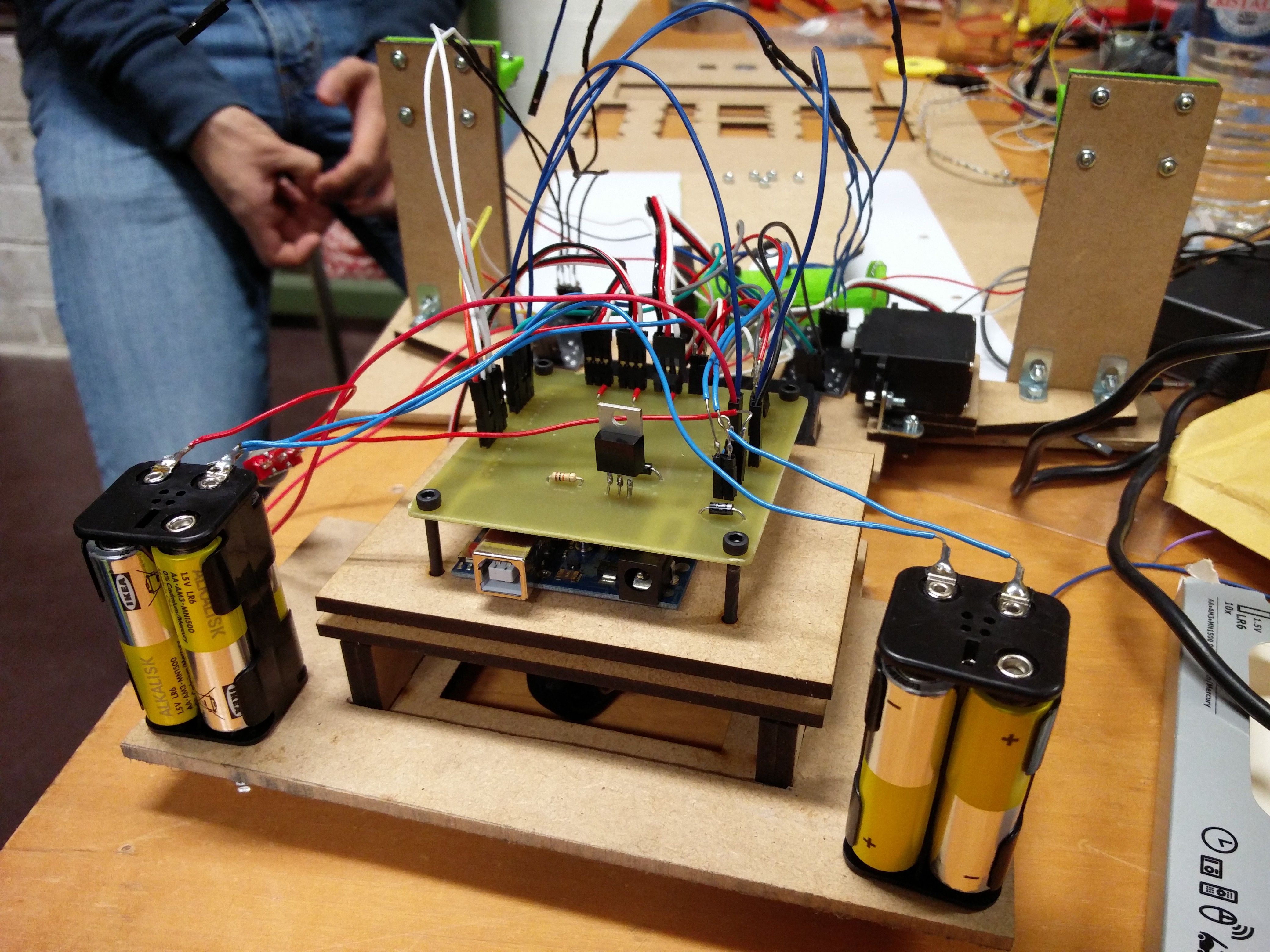
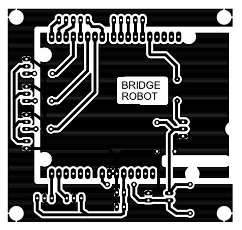
Once the board design is finished, the printing design looks like the one in the picture below.
The picture below shows the printed PCB with the different components placed on it.
Software
The functions for the control of the robot are written using the Arduino IDE version 2:1;0.5+dfsg2-4. The different files can be found in the Files section.
Test codesFirst of all, all the electronic components are tested separately with a test code to ensure that they are working properly. It allows also to detect if a component is not working as it should. So if an issue occurs during the coding of the whole robot or during the test phase of the robot, codes to check everyting are ready.
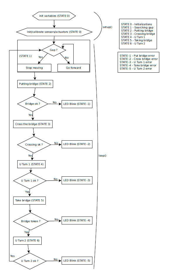
Final codeThe final code which drives the whole robot is written in a way that the Bridge Robot is a state machine. Each different action that the robot has to make is represented by a state. It works like this :
- Current action not finished : remain in the same state
- Current action successfully terminated : change to the state of the next action
- Current action failed : change to a failure state
Note that the failure states could be an action to correct the failure of the previous action like a sort of fail-safe system. In the present case, it just stops the robot waiting for a shut down.
In reality, all the fail states are not implemented in the code. It is something that still need to be done. It is not essential for the robot to work but it adds some stability and security to the robot.
Budget
| Material | Quantity | Price/unit (€) | Reference |
|---|---|---|---|
| MDF (90cmx30cm) | 2 | < 5.60 | http://www.castorama.fr/store/rechercher/MDF?osearchmode=tagcloud |
| Manufacturing process | Quantity(g) or Time(min) | Price | Reference |
|---|---|---|---|
| 3D printing | 85.85 g | 0.04€/g | / |
| Laser cutting | 10 min | 5 €/10 min | http://www.fablab-ulb.be/ |
For the 3D printing, ths cost is evaluate in function of the quantity of used matter while for the laser cutting, the price depends on the used time on the laser cut machine.
| Electronic component | Quantity | Price/unit (€) | Reference |
|---|---|---|---|
| GP2Y0A21YK0F Infrared sensor | 2 | 10.57 | http://befr.rs-online.com/web/p/reflective-optical-sensors/6666564/ |
| TCS3200 Color sensor | 2 | 10.85 | http://www.befr.ebay.be/itm/TCS230-TCS3200-Farb-Erkennung-Sensor-Modul-Detector-Color-Recognition-Arduino-/171747955293 |
| TIP120 transistor | 1 | 0.427 | http://befr.rs-online.com/web/p/darlington-transistors/7743653/ |
| 10k resistor | 1 | 0.016 | http://befr.rs-online.com/web/p/through-hole-fixed-resistors/7077745/ |
| 1N4007 diode | 2 | 0.03 | http://befr.rs-online.com/web/p/rectifier-schottky-diodes/7384724/ |
| Futaba S3003 servomotor | 1 | 9.99 | http://www.miniplanes.fr/servos/futaba/servo-s3003-futaba-p-2704.html |
| Futaba S3003 servomotor | 2 | 11.95 | https://www.parallax.com/product/900-00005 |
| Arduino UNO | 1 | 23.9 | http://www.conrad.be/ce/nl/product/092024/Arduino-Uno-development-board?ref=searchDetail |
| 1.5V AA battery | 8 | 0.175 | / |
| 4-Battery holder | 2 | 0.54 | / |
| Printed Circuit Board | 1 | / | / |
| Mechanical components | Quantity | Price/unit (€) | Reference |
|---|---|---|---|
| Bearing | 1 | 2.05 | http://befr.rs-online.com/web/p/angle-brackets/0427991/ |
| Bracket | 10 | 0.15 | http://befr.rs-online.com/web/p/ball-bearings/6190086/ |
| Castor wheel | 1 | 1.5 | / |
| K'nex wheel | 2 | 1.3 | / |
| Counterweight | 1 | 0.25 | / |
The total cost of the robot is equal to 131.15€, which is under the authorized limit (200€).