Welcome to our
Cocktail Machine report!
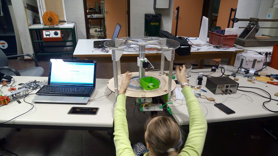
This website is made in order to show our work on the making of a cocktail machine.
Mechanics
Here you will find all
Mechanical parts
(and our choices)
Design
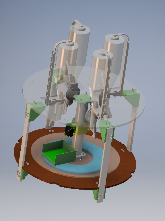
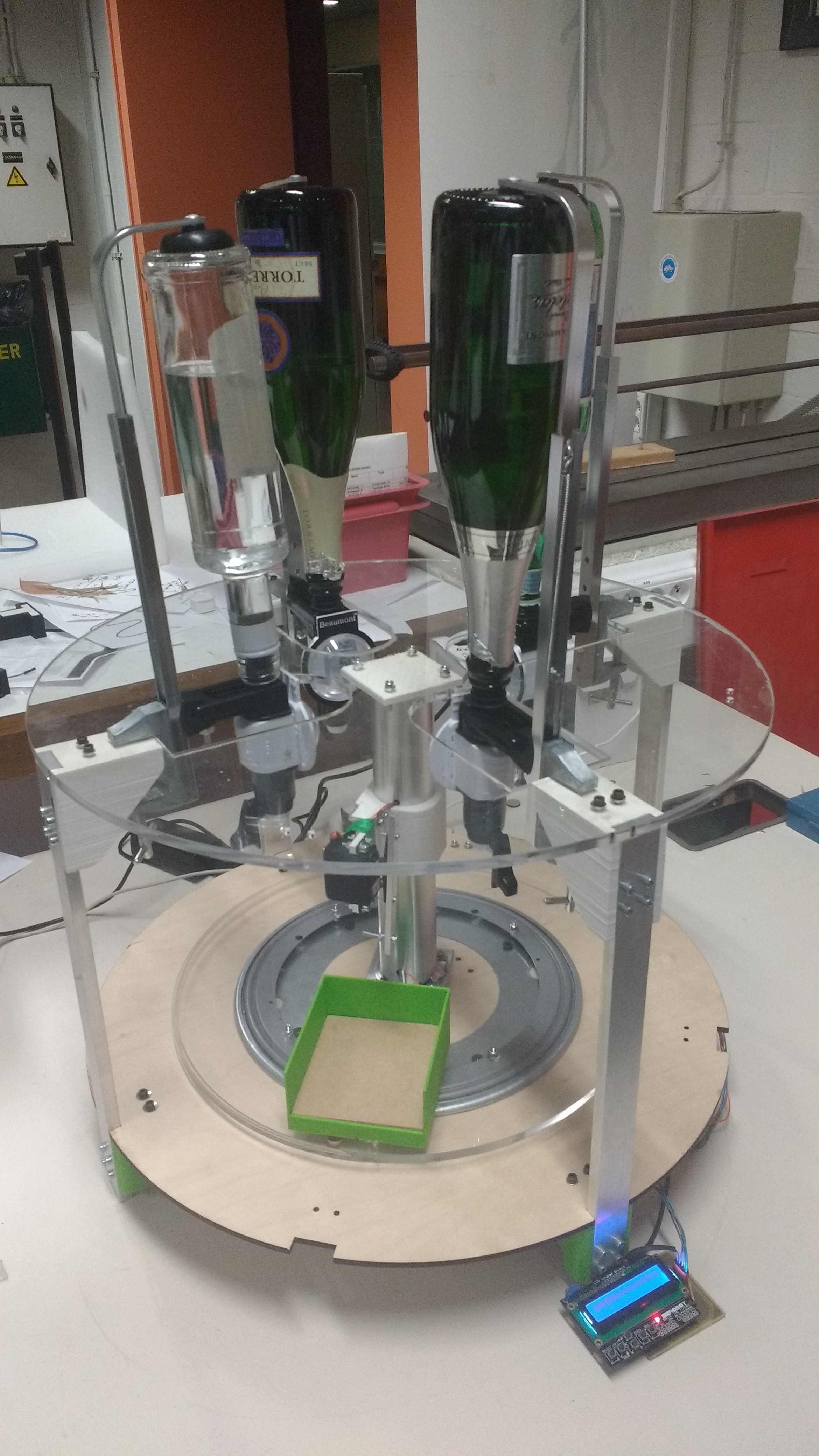
For the prototype, a rounded model was chosen because this looks nicer than the standard models where all the drinks are ordered in a row. The objective for this machine was to be able to make coktails using 4 bottles :
First of all, we had to choose the way to control how the liquid would go from the bottle to the glass. We decided that liquid dispensers were better than peristaltic pumps because they are much cheaper and faster.
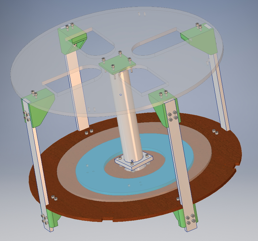
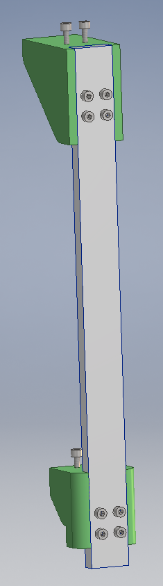
Afterwards, to put the different drinks inside the glass, either the bottles or the glass should be able to turn around the central axis. Because of the big inertia difference, it was chosen to make the glass turn. The prototype was designed on a microwave style. A plate on which the glass is put will turn, and an upper and a lower plates will be used for the support. See next figure :
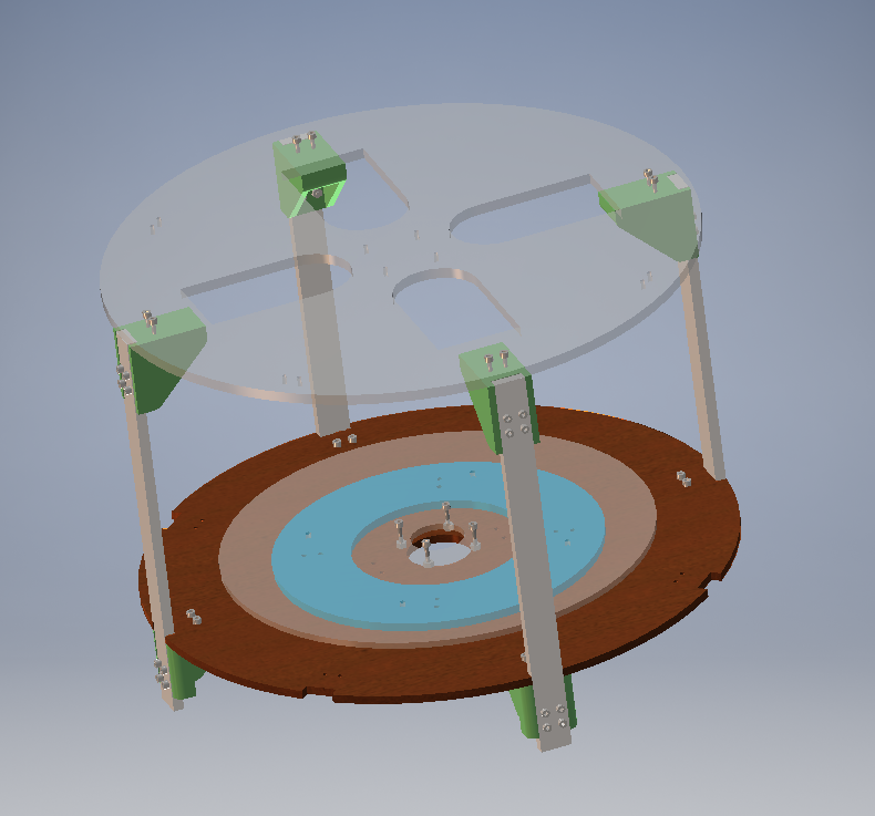
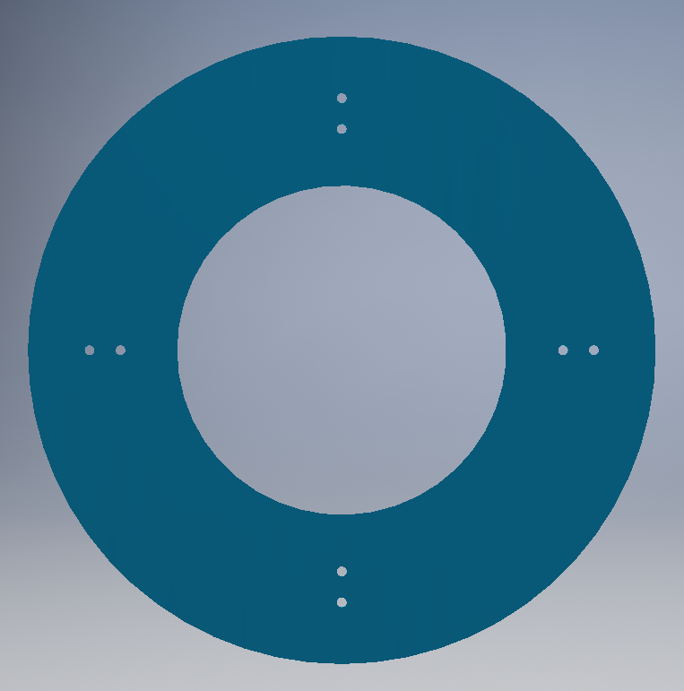
To make the middle plate turn, some bearing should be used. The cheapest way would have been to use 2 or 3 wheels. However, this doesnŌĆÖt work really well for a rotating system. Another possibility was to buy a mechanism called ŌĆśLazy SuzanŌĆÖ. This is a rotating tray placed on a table and used to make a turning plate with cheese for example. Inside this, there are many small balls used to make the friction coefficient as small as possible. Moreover, this system only costs 10 to 20€. This is why we decided to use it instead of doing our own system that wouldnŌĆÖt have been cheaper, and may not have worked better. In the drawing, it is simplified and represented as a blue circle. Only the attachment holes are represented.
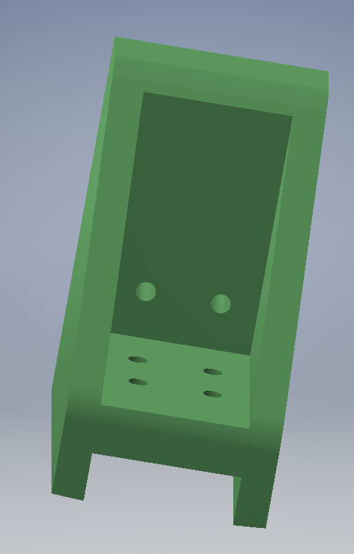
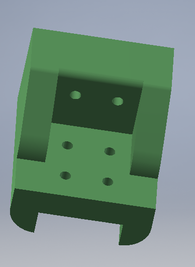
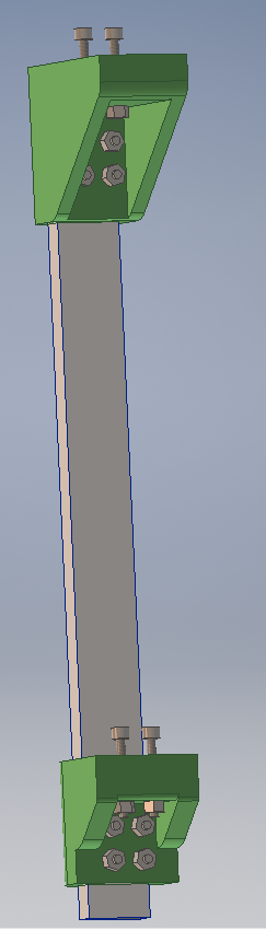
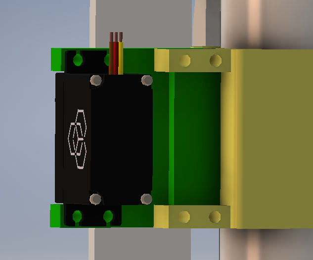
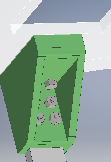
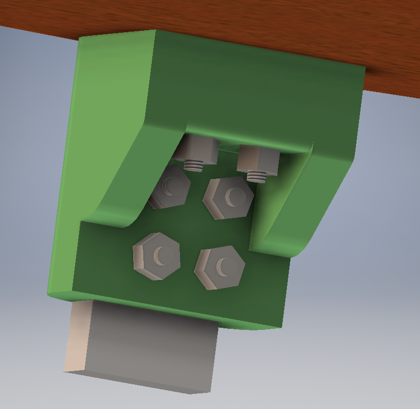
The hinges to attach the 4 aluminium bars to the plates can be 3D printed. Those used in the downside of the machine differ from the ones on the upperside, because there will be more weight on them. Therefore, they had to be more rigid. The upper ones have a longer arm because the design was made so that the bottles could rest directly on the hinges to avoid all the forces to push on the turning plate. You can see the pictures of the hinges (The two next pictures) An Ultimaker 2 was used to print all the 3D parts. On the side of the bars, 4 screws were used to make the support much stronger.
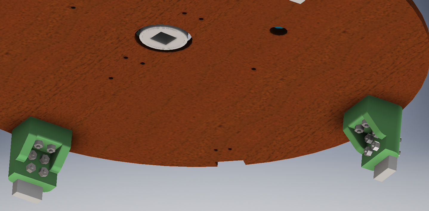
The materials and the thicknesses used for the different plates differ. The one above is made of plexyglass to make the glass visible, and the thickness used is 8mm. The highest thickness was chosen to make sure that the plexy would not break. The 2 plates used downside should be made out of some material that can get wet. Berk wood and Plexy were used because there was some plexy left from the plate, and the Berk because of the low price. The thickness is here not that important. There is not too much weight putted on this plates and if the stucture is not strong enough, extra support can be added on the ground. (next picture) There are some extra cuts made in the wood plate for this reason.
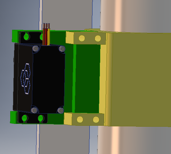
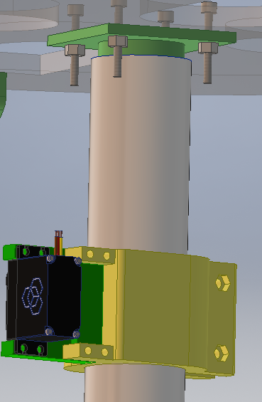
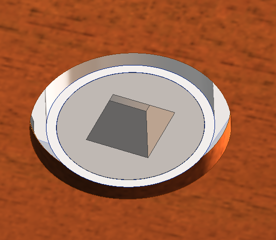
In the middle, there is an aluminium cylinder to which the servo motor will be attached. On the servo, a lever arm will be placed so this can push on the dispensers. In the design there is a universal piece made to attach on the cylinder. On this one, different attachment could be put to change the distance between the middle of the cylinder and the servo. See next picture :
In the upper plate, there is an extra cylindrical shape 3D printed which will enter inside of the aluminium cylinder to block aluminium cylinder from tilting. This was done as precaution to avoid the structure to move when the Servo will push on the dispensers :
The bottle holders are fixed at the side of the beams to avoid high forces in the middle of the upper plate.
The middle plate is turning using a stepper motor placed beneath the under plate. Here the use of gears was necessary : the stepper was not strong enough to make the plate turn without them. See next picture :

Structure
Plexiglass
Dispenser
Electronics
To build our Cocktail Machine, we have used a stepper motor, a servo motor and a weight sensor. The stepper is used to make the central plate on which the glass is turn around the central axis of the machine. The servo is used to make an arm pushing on the liquid dispensers attached under the bottles so that the liquid falls into the glass. Finally, the weight sensor is used to detect whether this is a glass on the plate, and to check that the bottles are not empty.
In this section, you will find every electronic components used in the cocktail machine as well as a description of their usufulness and why there where chosen.
LCD Shield
Although the LCD is not a sensor, it comes on a shield with several buttons that are used to select the cocktail the machine will do.
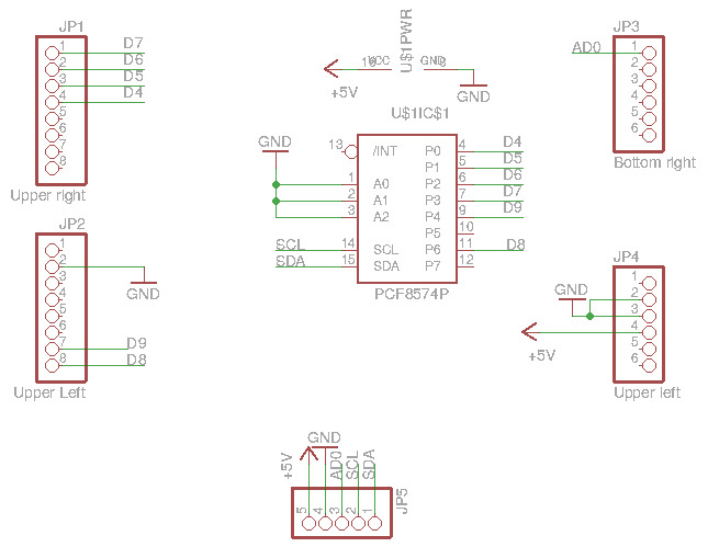
For this project, a recycled DFROBOT LCD Shield has been used. Unfortunately, this shield will not let anough availables pins for the arduino to controll all the other electronic components. A method to connect a LCD to the arduino with only 2 pins (using the library ŌĆ£LiquidCrystal_I2CŌĆØ was found on the internet. We just needed to apply it on the shield. Using the electric scheme of the DFROBOT (found on dfrobot ), we built a PCB which will connect the shield to the arduino with only 5 pins. Two of them were for the power input (0/+5V) and could also be used for other component, and the other where A0 for all the buttons (already implemented in the shield) and A4,A5 for the screen himself.
In order to connect the lcd with 2 pins, one component was needed : the PCF8574 : a remote 8-bit I/O expander for I2C bus. The plan of the pcb can be seen on the next picture.
For the use of the buttons, the code given on the shield website was used.
LEDs
Arduino
The first part about the electronics was to choose a micro-controller. Our choice went on an arduino for several reason. Despite the fact it is a quite ŌĆ£simpleŌĆØ micro-controller, it was good enough to handle the action we needed. Moreover, it is open-source making the coding of the component much easier since we could look on the internet for some example and hints. The last reason for us to take an arduino is that it is quite cheap and that will permit us to allow our budget to some more important parts.
Weight Sensor
For a matter of security for the electronics equipment and to avoid waste, a weight sensor was used to detect if a glass was in the machine. This sensor allow also to say if one of the bottle is empty as the weight on it wonŌĆÖt change if the glass doesnŌĆÖt fill. This will allow to send an alert for the user saying that he will have to change the bottle.
Positions Sensors
The last concern we had with our machine was that we wanted to be sure the glass is on the right position before the alcool begin to flow. In order to check that, we put a simple knob which will be pressed by some bump on the lower support whenever the glass is under a bottle. )
Memory
The cocktail machine need to remember the quantity of liquid that remain in each bottle. This will ensure that each cocktail of the database can be delivered. If a bottle is empty, the software will ask the user to replace the empty bottle and will also ask him the capacity of the bottle in order to keep the counts right.
One main concern was when we shut down the cocktail machine. We wanted it to be able to remember the quantity in each bottle before it was shutted down. For this we will explore three solutions :
In order to remember de fulfillment of the bottles, the only need was four variables in memory. One for each bottle. At start, they will be set to the quantity contained in each bottle. For every cocktail, the corresponding variable will be decremented until the selected cocktail could not be made.
SD card
This solution is interesting to implement but it is too heavy for the only four memory cells needed.
Even if this solution was not used, some research were made. They include :
Theory
- EngineerGarage - SD-card interfacing project
- AVRProjects - Reading and writing sd card using atmega16
- Adafruit - Micro SD breakout board card tutorial
Pieces
Software by internet
One option was to make a server. This option is very cool because it permit to handle for example multiples cocktail machines at the same time. Another functionality of having a server is that all the machines can get an updated version of a cocktail database depending on the bottles in each machine.
However, this option is very expensive in time, and we will only have one prototype. Thus, it was shutted down.
If the server solution will be made for future generations of the machine. There will be the necessity for a connection to the internet. This connection can be made with an ethernet circuit or with a wireless circuit.
Arduino ROM
This was by far the best option when we need only four values to be stocked and no client-server architecture. The Arduino possess an EEPROM memory and it is accessed by the EEPROM.h library (which is really intuitive).
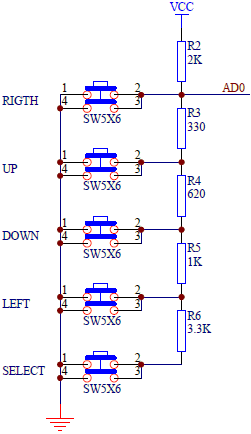
Control Buttons
Five control buttons were availables directly on the LCD shield. The PCB of the shield was observed carefully to understand how to get if a button is pressed. The circuit was really smart because it uses only one tension value to detect the push down of a button. This only need one pin on the arduino. The arduino code uses that feature.
Motors
Stepper
For the rotation of the bottom plate we need a motor that was:
- strong enough to make the plate, with the glass on top of it, rotate
- continuous
- easy to implement in the design
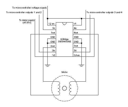
With this requirements we went to the project of previous years to see which motor we could use without buying a new one. We found an old stepper motor from tec (tec cba45-01101) we thought we could use. The disadvantage of recuperating this stepper was that it was so old we didnŌĆÖt find the datasheet for it on the internet, so we couldnŌĆÖt test the torque of it immediately. To test if the torque was high enough we made a driver for the stepper motor. It could be seen that we have a unipolar stepper because we have 6 wires, the motor can be seen as following electronic scheme:
Here you can clearly see that each coil has a extra wire in the middle. With this extra wire itŌĆÖs possible to make a stepper with higher resolution, but the torque isnŌĆÖt maximal because youŌĆÖre only using half of the coil at a time. Because we knew stepper motors arenŌĆÖt strong we had the idea to use the unipolar stepper as a bipolar one. Here we ŌĆ£forgetŌĆØ the 2 inner wires and use only the 2 outer ones so we use the whole coil. Now we need a way to switch the different phases on and off. This we did with a quadruple H-bridge (SN754410). The schematics can be seen in following picture:
This circuit worked good and so we used it in the final PCB as well. To power the stepper motor we first used an adjustable voltage regulator, because the nominal voltage was only 3V and our supply delivered 5V. The regulator we had chosen was the LM338T, this regulator could deliver the 1A and goes down to 1,2V.
Finally, we found out that we needed a higher voltage in order to make the plate rotate. We thus use now a professional stepper driver.
Servo
To get the liquids from the bottle into our glass we need a lifting mechanism (see mechanical design). Thanks to our calculations we knew that we needed a lot of torque to let this mechanism work. Therefore we used the [NAME SERVO MOTOR], this servo can deliver up to [TORQUE SERVO] what enough for our lifting mechanism. The current that this servo needs is [CURRENT SERVO]A and itŌĆÖs works on 5V. For this reason we can directly use our power supply of 5V to power the servo.
PCB
WhatŌĆÖs a mechanical design without a PCB?!?
Main PCB
After we tested every circuit separately on a breadboard we were able to print our PCB. The design was made in EAGLE and can be seen in following figure:
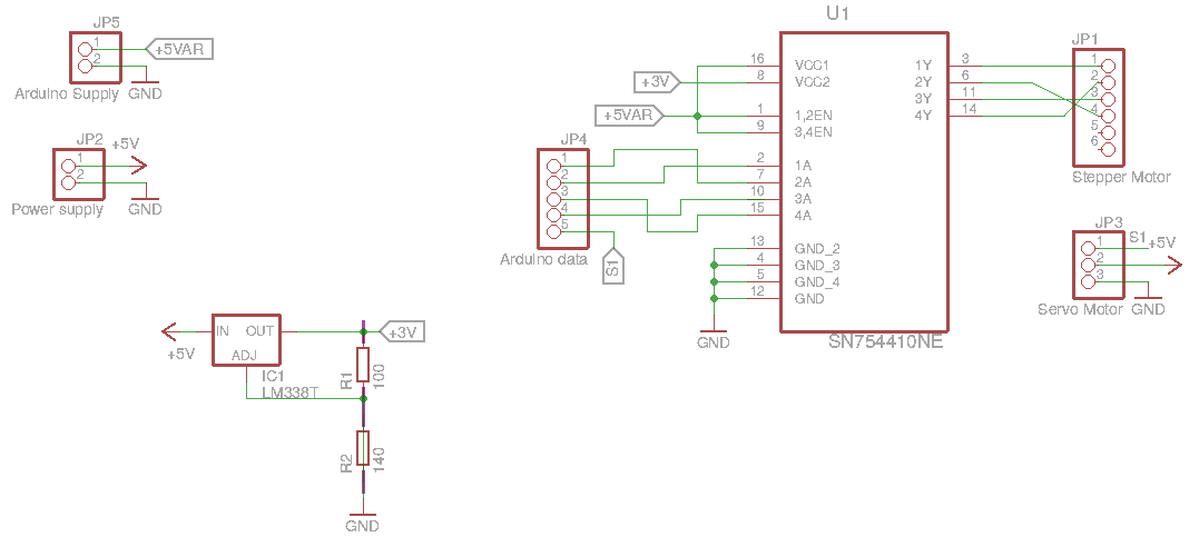
In the figure above we see: 1. Bottom left: the voltage regulator with 2 resistors to set the output to 3V. 2. Right: the connectors for the servo and stepper motors 3. Left: the power supply of 5V and the arduino 5V (for the reference in the H-bridge) and the ground (all grounds need to be connected) 4. middle left: the data pins connected to the arduino (4 for the stepper and 1 for the servo) 5. middle right: the H-bridge to drive our stepper
LCD PCB
On this circuit we can see the PCB in the middle. The four connectors left and right are these on which the shield will be plugged. They are positionned so they can reproduce all the output-pins of an arduino (on which the shield is supposed to be plugged. Finally, the bottom connector is the one who will be connected to the arduino. SCL and CDA are the analog pins of the arduino A5 and A4 respectively.
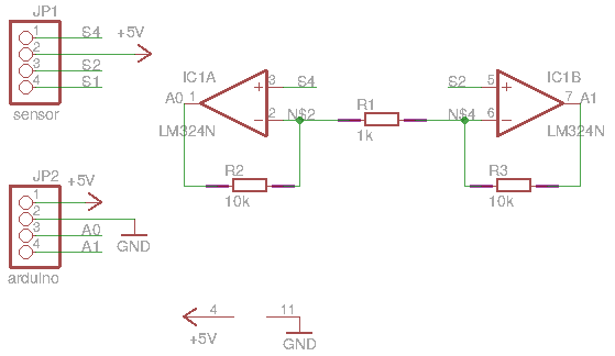
Weight Sensor PCB
On this pcb, the weight senor is connected to the arduino. The S1 pin of the weight sensor is not used while 4 pins of the arduino are used. The 5V and the gruod are common to the all electronic circuit and 2 analogs pins of the arduino are used.
Software
A machine with a cool design and a cool electronics is fun.. But, without the software it is useless. ThatŌĆÖs why a cool software was made in order to make it all work and let the user drink.
Arduino application
Cocktail database
An efficient data structure is made in order to register the recipes of every cocktails.
Adding cocktails is as easy as
const int NUM_COCKTAILS = 5;
cocktail cock[NUM_COCKTAILS];

void makeDatabase() {
  cock[0].insert("Name 1",1,1,1,1);
  cock[1].insert("Name 2",0,0,0,1);
  cock[2].insert("Name 3",1,0,0,0);
  cock[3].insert("Name 4",0,2,0,1);
  cock[4].insert("Name 5",0,0,0,4);
  cock[5].insert("Name 6",1,0,0,3);
}
We can see that it is really easy to add recipes. One only need to change the number of cocktails, set a name and the quantities of every bottles. The quantities are multipliers of 50ml in quantity. Thus, for the cocktail 6 its name is ŌĆ£Name 6ŌĆØ and it is composed of 50 ml of the bottle one and 3 times 50 ml of the bottle four.
Behind all of that there is only a final state machine!
All the code is based on a simple state machine with only two states :
- INIT : Initial state where we show the menus.
- CORE : The principal state where we actionate the sensors/motors to make the cocktail.
In the initial part, the user will be asked to select a cocktail. If for the selected cocktail there is not enough liquid in the bottles remaininig, the code will enter in a subroutine where it will ask the user to replace empty bottles needed for the cocktail.
And the memory part
When we are not making a cocktail, the user can always use the left button to know how many liquid remains in the bottles.
The quantity of liquid is recorded even when the system is shutted down. This mean that the system will remember how many liquid rest in each bottle when it wakes up. If the user want to change a bottle even if it is not empty (simply because the bottle is too old or he wants to change the alcool) the right button allows the user to reset the quantity of liquid in each bottle.
Android/iOS application
A smartphone application was considered but we did not had enough budget to use a Wifi shield nor enough pin on the arduino board. This can be a very good improvement for the next version of the machine.
You can find the code HERE
Video
Having an embedded media (photos and video) is often inflexible with a dynamic and responsive design.
Costs
Details of the costs can be found here
but in a nutshell :
-
52 € for the mechanics
-
144 € for the electronics
-
146 € of others (Alcool dispencer, Lazy Susanne, screws, etc.)
The total price will be 342 € if you want to make your own cocktail machine but in reality we have used a lot of parts that were in the lab. This decrease greatly the total cost.
Team Work
Our team is composed of three students from the Universitķ Libre de Bruxelles, and two from the Vrije Universiteit Brussel. During the whole project, the work has been dispatched between the members of the group so that everybody had something to do. We have discussed together during a long time to find a good design. After that, each of us did his own part as reported in the following┬Ā:
- Gevorg┬Ā: 3D printing, laser cutting and CAD
- Stein┬Āand Quentin: PCB design
- Stein : PCB assembly and circuit testing
- Daniele and S├®gol├©ne┬Ā: Programming
- Gevorg, Quentin and S├®gol├©ne┬Ā: Assembling
- Daniele┬Ā: Website and integration

Gevorg Demurchyan

Quentin Fesler


Stein Crispel