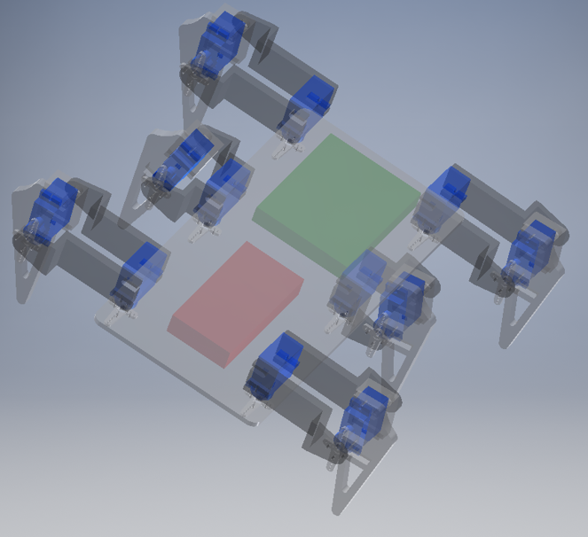
As Mechatronics is a multidisciplinary field so the visible goal of this project was to design a robot or Electro-mechanical machine. After looking through many projects and ideas we decided to make a Hexapod. Hexapod is a six legged robot. As we hexapod have six legs and it can be stabilized on three or more legs so it has great deal of flexibility how it can move in different circumstances. As it can be stabilized on three legs so it does not need all the legs to be stabilize. This kind of characteristics made us interested in choosing Hexapod as a project.
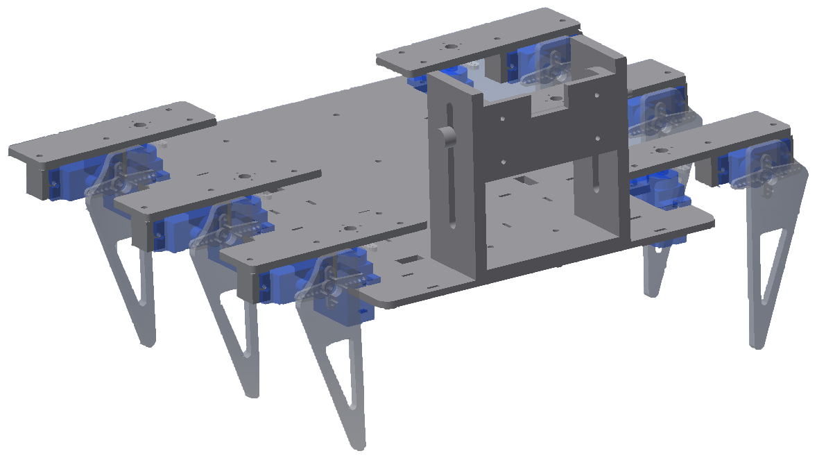
After choosing the project first task was to design simple mechanical structure. After trying many different design iterations we came up with simple mechanical design with six legs.
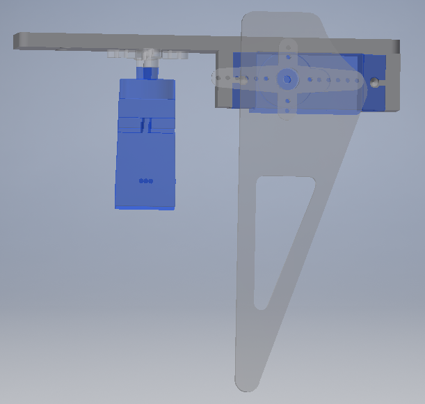
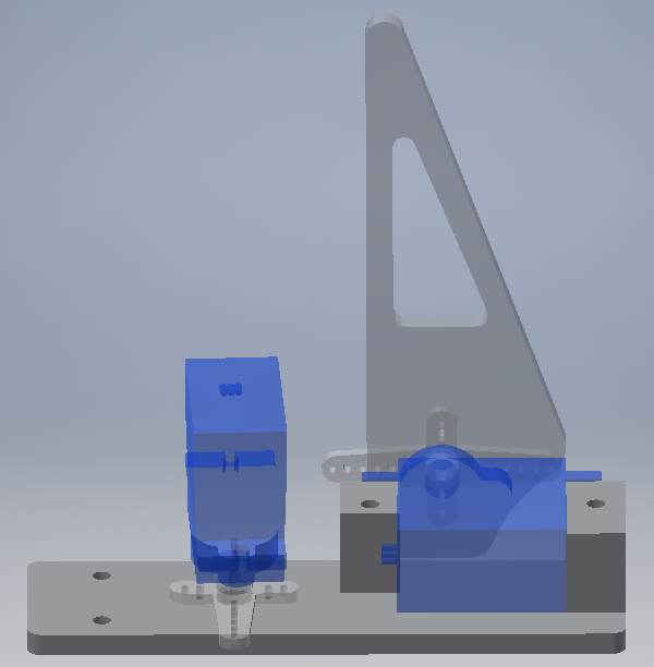
Each Leg contains two motors. One to move forward and backward. And another to lift the leg from ground. For reference the motor which will move forward and backward is called ‘shoulder motor’ and the motor to lift the leg is called ‘elbow motor’ As it can be seen in the pictures below that the robot has a platform on which shoulder motors are attached. These motors are also responsible for turning the robot. On these motors a shoulder is attached as seen in picture below. At the end of shoulder a elbow motor is placed. Elbow motor is attached with shoulder with help of two small holders And nuts and bolts.
There is enough space left between left and right legs to put circuits in it. At the front side of robot a structure is added to hold Ultra-Sonic sensor. Before this version 2 more designs were made. In the first design motor shaft were upside down so all the forces were acting on shaft which was not a good idea. The design picture is attached. In second iteration of design the design is same as the final design but the attachment of elbow motor was directly to the shoulder without help of any holders.
After creating a mechanical structure next step was to choose motors. After careful analysis of torques in shoulder and elbow joints we decided to choose servo motor SG90 9g. Specification of motor are given below:
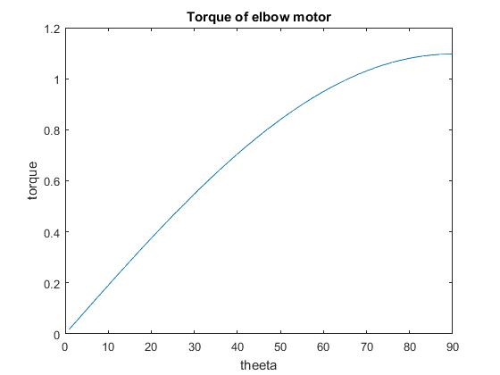
Calculation for torque analysis are done on MATLAB and graphs are attached. As it can be seen that the maximum torques in elbow and shoulder are way less than the stall torque of the current so we can use these motors safely.
In the analysis part will be explained like a step necessary in order to make sure that all the pieces of the robot are able to resist the stress.
The program used is ANSYS 15, in the module Workbench.
The 3 pieces that will be analysed are: the body bottom, the shoulder and the leg of the robot.
In each analysis, the only thing that will be proved is that each piece works in an allow zone before arrive to the fluent limit of the material.
The procedure to analyse all the pieces is the same:
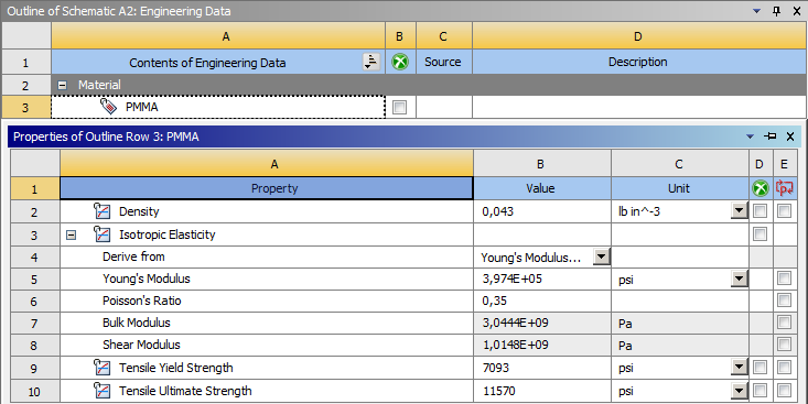
The material that has been used is the Acrylic, which properties are:
(PROPERTIES PHOTO)
In this piece, the fixed faces are the servo motors zone and the load is applied in the gravity centre of the body bottom which represents the weight of all the electronics components attached to it and the weight of itself.
(FIXED PHOTO)
(LOAD PHOTO)
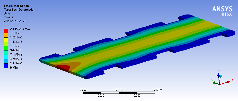
And the results are as follows:
(TOTAL DEFORMATION PHOTO)
The deformation is less than 1 mm, so the solution is admissible.
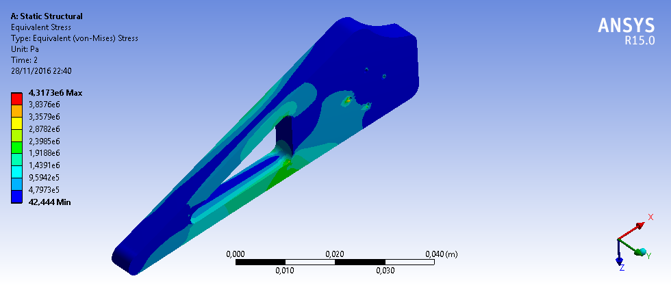
(EQUIVALENT STRESS PHOTO)
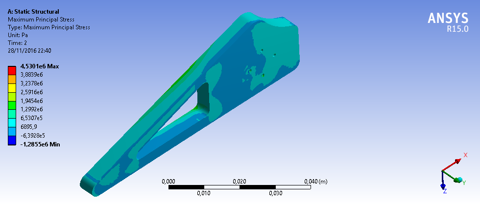
(MAXIMUM PRINCIPAL PHOTO)
In both kind of stress, the stress is lower than the Tensile Yield Strength so the material works in the elastic region.
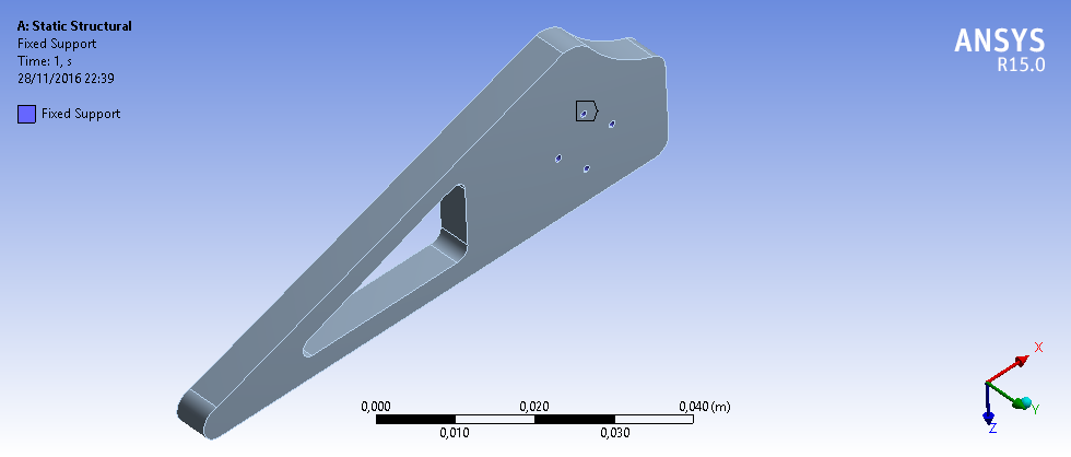
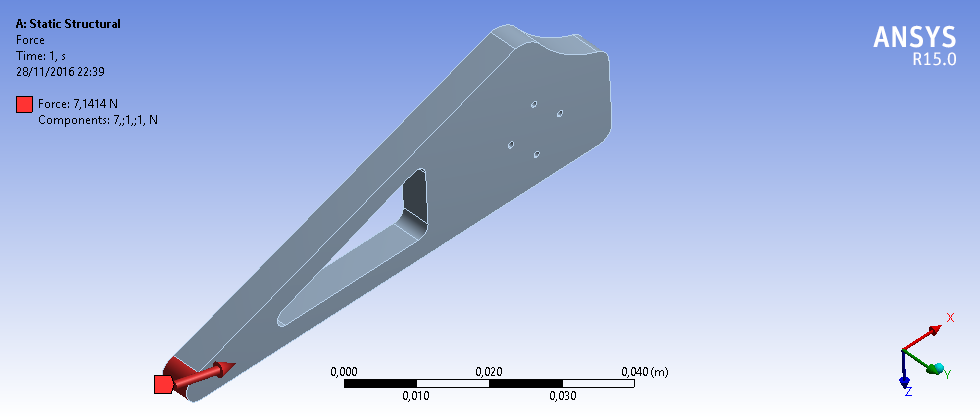
In this piece, the fixed faces are the screws attach zone and the load is applied in the end of the shoulder which represents the weight of the set servo motor plus the leg attached.
(FIXED PHOTO)
(LOAD PHOTO)
And the results are as follows:
(TOTAL DEFORMATION PHOTO)
The deformation is less than 1 mm, so the solution is admissible.
(EQUIVALENT STRESS PHOTO)
(MAXIMUM PRINCIPAL STRESS PHOTO)
In both kind of stress, the stress is lower than the Tensile Yield Strength so the material works in the elastic region.
In this piece, the fixed faces are the screws attach zone and the load is applied in the end of the leg which represents the weight of all the robot.
(FIXED PHOTO)
(LOAD PHOTO)
And the results are as follows:
(TOTAL DEFORMATION PHOTO)
The deformation is less than 1 mm, so the solution is admissible.
(EQUIVALENT STRESS PHOTO)
(MAXIMUM PRINCIPAL STRESS PHOTO)
In both kind of stress, the stress is lower than the Tensile Yield Strength so the material works in the elastic region.
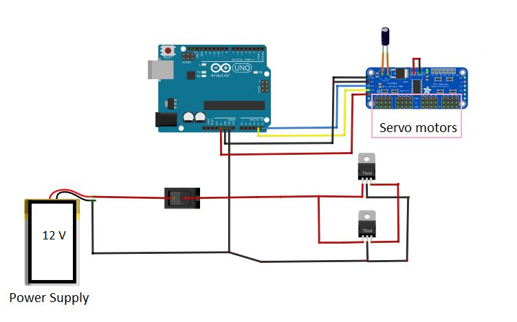
The basic connections that we have done are shown in the following picture. As it is shown, all the components are connected to the PCB.
So in this section, we are going to explain and define all the electronic used in this project and the circuit created.
Item Number | Quantity | Part Name |
---|---|---|
1 | 1 | Arduino UNO |
2 | 1 | Adafruit 16 Channels |
3 | 2 | Regulator Model 7805 |
4 | 12 | Micro Servo SG90 |
5 | 1 | Ultrasonic sensor |
6 | 1 | Button ON/OFF |
7 | 1 | Capacitor 1200 MF |
8 | 1 | Nunchuck |
9 | 2 | Resistors 220 Ohms |
10 | 2 | Led |
First part in electronics was to select the microcontroller which will control the robot. We decided to use Arduino Uno as it was available. Another motivation to use Arduino was that programming it is easy and lot of help is available online for it.
The problem with using Arduino Uno is that it has only 6 PWM output pins and the robot has 12 servos. To solve this problem we decide to use Ardafruit 16 channel servo controller. It can serially connect with Arduino and can control up to 16 motors at same time. To control the adafruit, we will need a specific arduino library.
This regulator can deliver up to 1.5 A of output current, allow to regulate the voltage and eliminate the noise. Two of these regulators have been integrated in parallel in the electronic circuit in order to give more current to the motors (3 A) and regulate the voltage between 5-6 V (the last two numbers of the model correspond to the voltage).
12 Micro Servo motors have been chosen for several reasons: tiny dimension (22.2 x 11.8 x 31 mm approx.), low weight (9 g), stall torque (1.8 kgf * cm. According to the stress analysis of the structure, this servo has the torque enough to move the hexapod) and operating voltage (5 V approx.)
An HC-SR04 ultrasonic sensor is used at the front of the robot to detect obstacles in front of robot. The specs are given below:
To control the hexapod, we decided to use a Nunchuck. Nunchuck is a controller that can be used for 5 movements: accelerometer, axis X, axis Y, button C and button Z. In this case, we have only use the movements from the axis X and Y to go forward, back and turn. To control the nunchuck, we will need a specific arduino library.
For this project we have chosen two resistors of 220 Ohms to protect two Led. These resistors are connected between the arduino and leds.
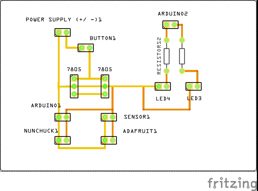
A PCB board is designed to supply power and ground to all components. 7805 regulator is used to regulate the voltage. All the components are joined to his board. Schematic is attached below.
The connections are shown in the following picture.
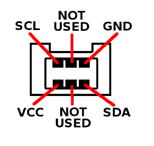
As we can see, Adafruit has 6 pin out. GND and Vcc are connected to the PCB. SCL is connected with pin A5 in the arduino and SDA is connected with pin A4. In order to give power to the board, the pin V+ is necessary to connect to 5V.
The sensor's pins are connected like this:
Before we start programming, we must understand how our robot will move. The hexapod will have 6 legs and these will be paired three by three, creating two groups. Looking at the following figure, this statement is better understood:
We decided to apply the following sequence to determine the movement of our hexapod:
Defined the movement, we had to face the calibration of the servos. Calibrating means finding the ranges of positions in which we want our motors move in.
Once the servos were calibrated, we proceeded to download the Adafruit and Nunchuck libraries to control the 12 motors at once through the Wii joystick.
Inside the nunchuck library, we had to look at the ranges for which we took values forward and backward to be able to perform functions.
Having all this clear, we proceeded to the programming. We have done a very simple programming, sequential and with functions that have allowed us to handle the hexapod as we wanted.
In the following code, we are going to talk about the function “go forward”. To see all the code, please download the “.ino” file.
We started by defining the libraries and the adafruit:
#include <Servo.h>
13 MECHATRONIC PROJECT: HEXAPOD
#include <Wire.h>
#include <Adafruit_PWMServoDriver.h>
//Adafruit declaration
Adafruit_PWMServoDriver servos = Adafruit_PWMServoDriver(0x40);
//Nunchuck declaration
WiiChuck chuck = WiiChuck();
After that, we have defined a vector which contains all the servo positions (values obtained by the calibration). As it is shown Fwd = mueve shoulder forward, Bwd = mueve shoulder backward , Hor = pon las legs horizontal and Ver = pon las legs vertical.
// {0, 1, 2, 3, 4, 5, 6, 7, 8, 9, 10, 11, 12}
unsigned int FWD[] = {0, 190, 0, 185, 0, 200, 0, 160, 0, 130, 0, 110, 0};
unsigned int REST[] = {0, 160, 0, 150, 0, 170, 0, 185, 0, 155, 0, 135, 0};
unsigned int BWD[] = {0, 120, 0, 120, 0, 140, 0, 230, 0, 190, 0, 165, 0};
unsigned int HOR[] = {0, 0, 120, 0, 170, 0, 300, 0, 300, 0, 340, 0, 120};
unsigned int VER[] = {0, 0, 290, 0, 350, 0, 130, 0, 130, 0, 135, 0, 290};
Following, we have defined the variables that we are going to use:
int i=1;
// LED declaration
int moving = 4; // led that shows that the robot is in a moving command
int NOgo = 5; // led that shows there is an obstacle ahead
// Sensor declaration
#define echoPin 3 // Echo Pin
#define trigPin 2 // Trigger Pin
long duration, distance; // Duration used to calculate distance
We define the setup where we initialize all the variables:
void setup() {
Serial.begin (9600);
pinMode(trigPin, OUTPUT);
pinMode(echoPin, INPUT);
pinMode(moving, OUTPUT);
pinMode(NOgo, OUTPUT);
chuck.begin();
chuck.update();
servos.begin();
servos.setPWMFreq(60); //Frecuecia PWM de 60Hz o T=16,66ms }
We define the function “go forward”:
void GOFWD(){
digitalWrite(moving, HIGH);
Serial.println("He entrado en GOFWD");
Go up 3 legs
servos.setPWM(2,0,HOR[2]);
servos.setPWM(6,0,HOR[6]);
servos.setPWM(10,0,HOR[10]);
Serial.println("Arriba 2 6 10");
delay(250);
//Move forward 3 shoulder
servos.setPWM(1,0,FWD[1]);
servos.setPWM(5,0,FWD[5]);
servos.setPWM(9,0,FWD[9]);
Serial.println("Delante 1 5 9");
delay(250);
//Go down 3 legs
servos.setPWM(2,0,VER[2]);
servos.setPWM(6,0,VER[6]);
servos.setPWM(10,0,VER[10]);
Serial.println("Baja 2 6 10");
delay(250);
//Go up 3 other legs in order to avoid friction
servos.setPWM(4,0,HOR[4]);
servos.setPWM(8,0,HOR[8]);
servos.setPWM(12,0,HOR[12]);
Serial.println("Arriba 4 8 12");
delay(250);
//Move 3 shoulder back in order to body go forward
servos.setPWM(1,0,REST[1]);
servos.setPWM(5,0,REST[5]);
servos.setPWM(9,0,REST[9]);
Serial.println("Atras 1 5 9");
delay(250);
//Move forward 3 other shoulders
servos.setPWM(3,0,FWD[3]);
servos.setPWM(7,0,FWD[7]);
servos.setPWM(11,0,FWD[11]);
Serial.println("Delante 3 7 11");
delay(250);
//Go down 3 legs
servos.setPWM(4,0,VER[4]);
servos.setPWM(8,0,VER[8]);
servos.setPWM(12,0,VER[12]);
Serial.println("Abajo 4 8 12");
delay(250);
//Go up 3 other legs in order to avoid friction
servos.setPWM(2,0,HOR[2]);
servos.setPWM(6,0,HOR[6]);
servos.setPWM(10,0,HOR[10]);
Serial.println("Arriba 2 6 10");
13 MECHATRONIC PROJECT: HEXAPOD
delay(250);
//Move 3 shoulder back in order to body go forward
servos.setPWM(3,0,REST[3]);
servos.setPWM(7,0,REST[7]);
servos.setPWM(11,0,REST[11]);
Serial.println("Atras 3 7 11");
delay(250);
digitalWrite(moving, LOW);
Serial.println("He salido de GOFWD");}
And also here is the programme for the sensor
void SENSOR(){
digitalWrite(trigPin, LOW);
delayMicroseconds(5);
digitalWrite(trigPin, HIGH);
delayMicroseconds(5);
digitalWrite(trigPin, LOW);
duration = pulseIn(echoPin, HIGH);
distance = duration/58.2;
Serial.print("Distance:");
Serial.println(distance);
delay(250);}
And the programm for the nunchuck
void JOYSTICK (){
delay(20);
chuck.update();
Serial.print(chuck.readJoyX());
Serial.print(", ");
Serial.print(chuck.readJoyY());
Serial.print(", ");
Serial.println();}
We define the void loop (the function that is going to repit). Here we have called all the other functions created:
void loop(){
SENSOR();
JOYSTICK();
if(distance>20){ //CAN MOVE
if((chuck.readJoyY() > 100)&&(chuck.readJoyX() >
100)){
//nunchuck in topright corner
RESET();}
else if((chuck.readJoyY() > 100)&&(chuck.readJoyX() < -80)){
//nunchuck in topleft corner
RESET(); }
else if ((chuck.readJoyY() < -100)&&(chuck.readJoyX() < -100)){
//nunchuck in bottomleft corner
RESET(); }
else if ((chuck.readJoyY() < -100)&&(chuck.readJoyX() > 100)){
//nunchuck in bottomright corner
RESET();}
else if ((chuck.readJoyY() > 122)){
GOFWD(); }
else if(chuck.readJoyY() < -131){
GOBWD();}
else if ((chuck.readJoyX() < -122)){
GOLFT();}
else if ((chuck.readJoyX() > 129)){
GORHT(); }
}
if(distance<20) //CAN'T MOVE
{
RESET();
digitalWrite(NOgo, HIGH);
delay(250);
digitalWrite(NOgo, LOW);
delay(250);
digitalWrite(NOgo, HIGH);
delay(250);
digitalWrite(NOgo, LOW);
delay(250);
digitalWrite(NOgo, HIGH);
delay(250);
digitalWrite(NOgo, LOW); }
Serial.println("CicloTerminado");
Serial.println(i);
i++;
}
In this section we are going to talk about the possible improvements that our robot could have:
Atif Hussain Syed
Vicente Lafarga Nebot
Álvaro Gil Rodríguez
Maria Dolores Rodriguez pérez