Electronical Design
The purpose of the
electronic board is to control 4 bipolar stepper motors by means of a
microcontroller. The used microcontroller is the PIC 16F877A.
So in fact 4 similar circuits had to be designed, 1 for each stepper motor.
Some research on the web quickly brought us to a chip that would make things
a lot easier:
The chip L297 is used and works together with the chip L298. A very detailed
info about these chips can be found in the datasheets on the
"links" page of this site.
The L297 is a handy chip because it has all the easy input ports. For
example instead of sending a sequences of 4 bits, only a clock signal is
required to make the stepper motor rotate. To make it rotate in opposite
direction, it's not necessary to change the sequence but just change one
input from the chip from 1 to 0 or vice versa. The chip can only be fed by
5V and cant produce a high current at its output. That's why it works in
combination with the L298 chip. This is a power chip that has to be fed with
a voltage of 5V, but is also fed through another port with a voltage between
5V and 32V, which is used to power the steppers. As you see these values are
much higher. This way the motors can get the needed power. Because it's
always better to work with only 1 supply, and the 2 chips had to be fed by
different voltages, we had to use the L7805 chip which regulates its output
voltage at 5V exactly, while its input can be nearly anything higher than
5V. We used some capacitors to make sure the noise on the voltage is
stable.
The PIC microcontroller must be fed with 5V also, so another 5V regulator
was used for the PIC. For safety reasons we fed each chip with a different
regulator. They are really cheap and it makes sure we don't overload each
regulator.
The main reason to use this circuit is also because there's a built-in
chopper in the L297 chip. With this tool it's possible to control the amount
of power the attached motor receives from the supply. The controlling of the
L298 happens through the L297 chip which is in its turn controlled by the
PIC microcontroller.
Following picture shows the schematic for 1 stepper motor.
The left chip on the schematic is the L297 and the right chip is the L298.
As you can see the input port 18 on the L297 is the clock. The faster the
clock, the faster the motor will work. Input port 19 can make us choose
whether we use the motor in half step or full step mode. We always use full
step mode, which delivers more power to the motors, while half step mode
would give a smoother turning. Input port 10 is the enable port. If this
port is set to 0 then the motors get zero power. Set this port to 1 and it
will work again. Port 17 is the clockwise / counter clockwise port (CW/CCW).
Switching its value makes the motor rotate in opposite direction. Port 20 is
the RESET port. It must be set to zero. Else the motor will always receive
the bit sequence " 1 0 1 0 " and block. This has no practical use for us.
Port 15 is called Vref. When the voltage Vref is lower than the voltage it
receives through port 13 and 14 (SEN1 and SEN2) the motor will receive less
power due to the working of the chopper of the 297. So actually, port 15
enables the chopper mode. is very handy because it takes care of our problem
that the motors shouldn't use much power when they're not moving and as
explained in the motor part of the hardware page
we can't just disable the motors when they don't have to move, since then
they'll skip steps. These ports are the ports we control with the PIC
microcontroller.
Port 3 called HOME is an output port on the L297 and gives a pulse every
time the motor passes the sequence "1 0 1 0". This is useful to count the
steps the motor has made. First we thought we could use this, so we made a
connection with this and the PIC but it's of no practical use since the PIC
already knows how many steps the motor makes since the PIC itself takes care
of the clock-signal. We now just count the pulses we have given. The
L297 then passes the 2 phases on to the L298 chip which then chops the
output to the motors if asked from the PIC.
Port ENABLE on the L297 from each circuit is connected together with the PIC
so that all the motors are enabled and disabled simultaneously. Also the
RESET ports are connected together and controlled simultaneously.
Each motor is thus connected to the PIC by 6 connections: CLOCK, ENABLE,
RESET, CW/CCW, VREF and HOME. Since home isn't used, it shouldn't be
connected in later designs of this board. For the ENABLE and the RESET there
is for both functions only 1 connection on the PIC for all 4 motors, so not
many ports of the PIC are used for this. Each additional motor only uses up
3 additional ports on the PIC (HOME excluded) since ENABLE and RESET are
connected to the same ports as for the first motor. This also demonstrates
the use of the L297 chip because else there would be needed many, many more
ports per motor: 4 for the 4 bit sequence signal, plus additional ports for
the chopper function we would have to design ourselves.
This concludes the motor circuits.
Besides the 4 electronic circuits for the stepper motors there's also the
matter of connecting the PC to the electronic board. This happens through a
serial connection. So this had to be included in the electronic board as
well.
Also the so called ICSP connection was added. The purpose of the ICSP
connection is to program the PIC microcontroller without removing it from
the electronic board. By these means it's possible to eliminate the danger
of damaging the connections on the microcontroller that would occur by
always removing and replacing the PIC on the board.
The ICSP connection and the Serial connection could be copied from a demo
board made by Ronald Van Ham.
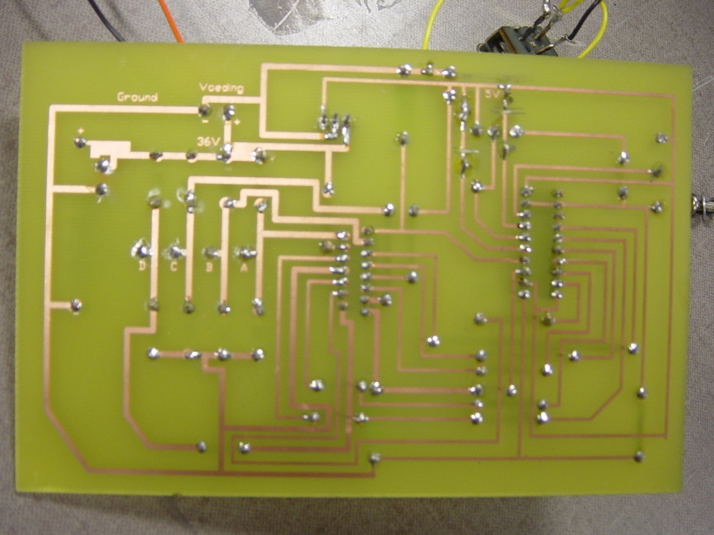
The making of:
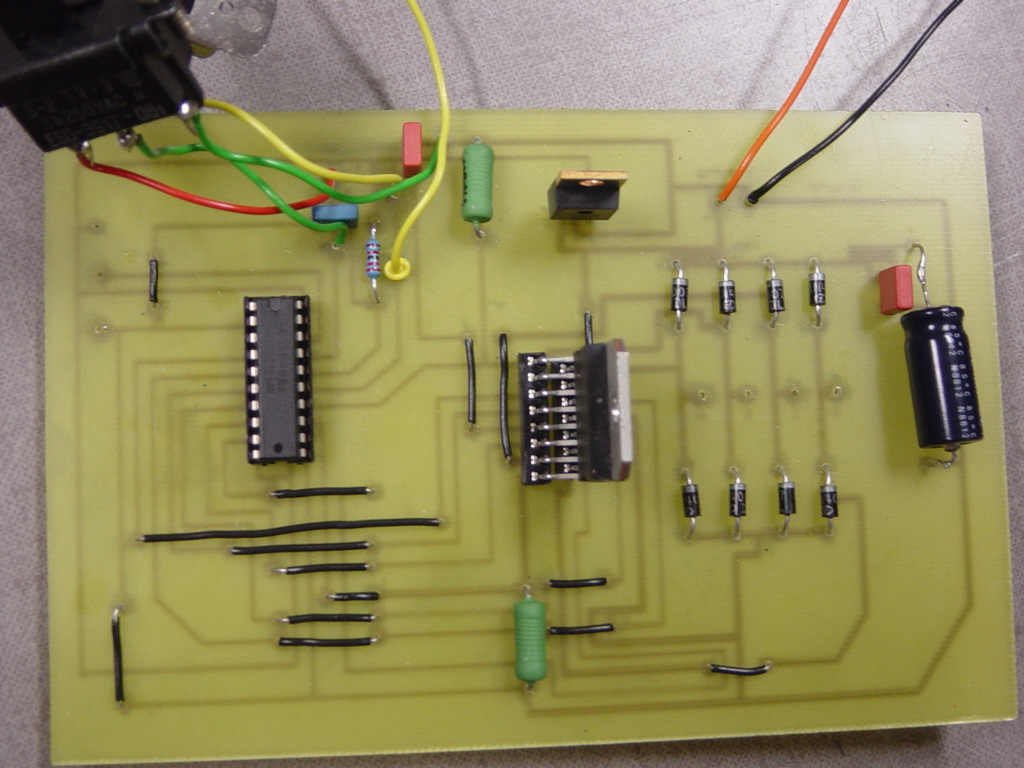
First we wanted to test the schematic we found. So we made our test-board.
Actually his is only used to control only 1 bipolar stepper motor, but
instead of a PIC microcontroller to control the L297 chip we used switches
and function generators. With this board we could test the abilities of the
motors. Seeing if the motors are damaged, or strong enough, without having
to program one bit in Assembler or Visual Basic.
This proved to be really handy.
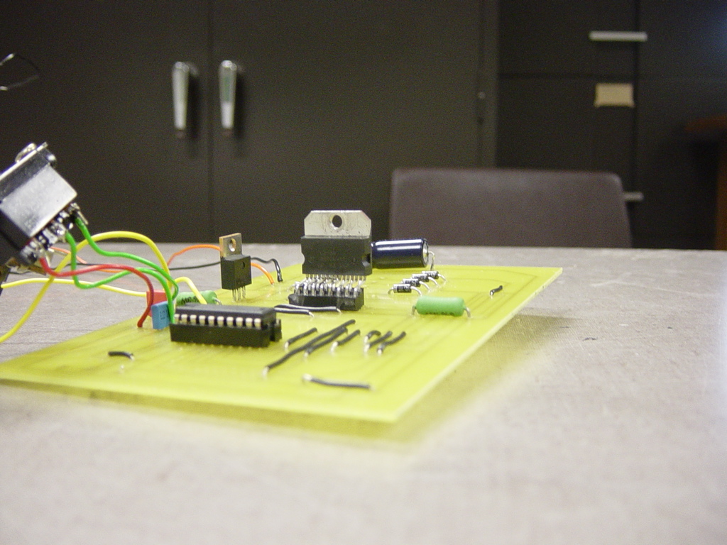
The result of the board is shown here.
When we agreed on the motors we would use and the fact that the test-board
works, we could confide in our abilities to make the larger board that would
contain the PIC and the circuits for each motor.
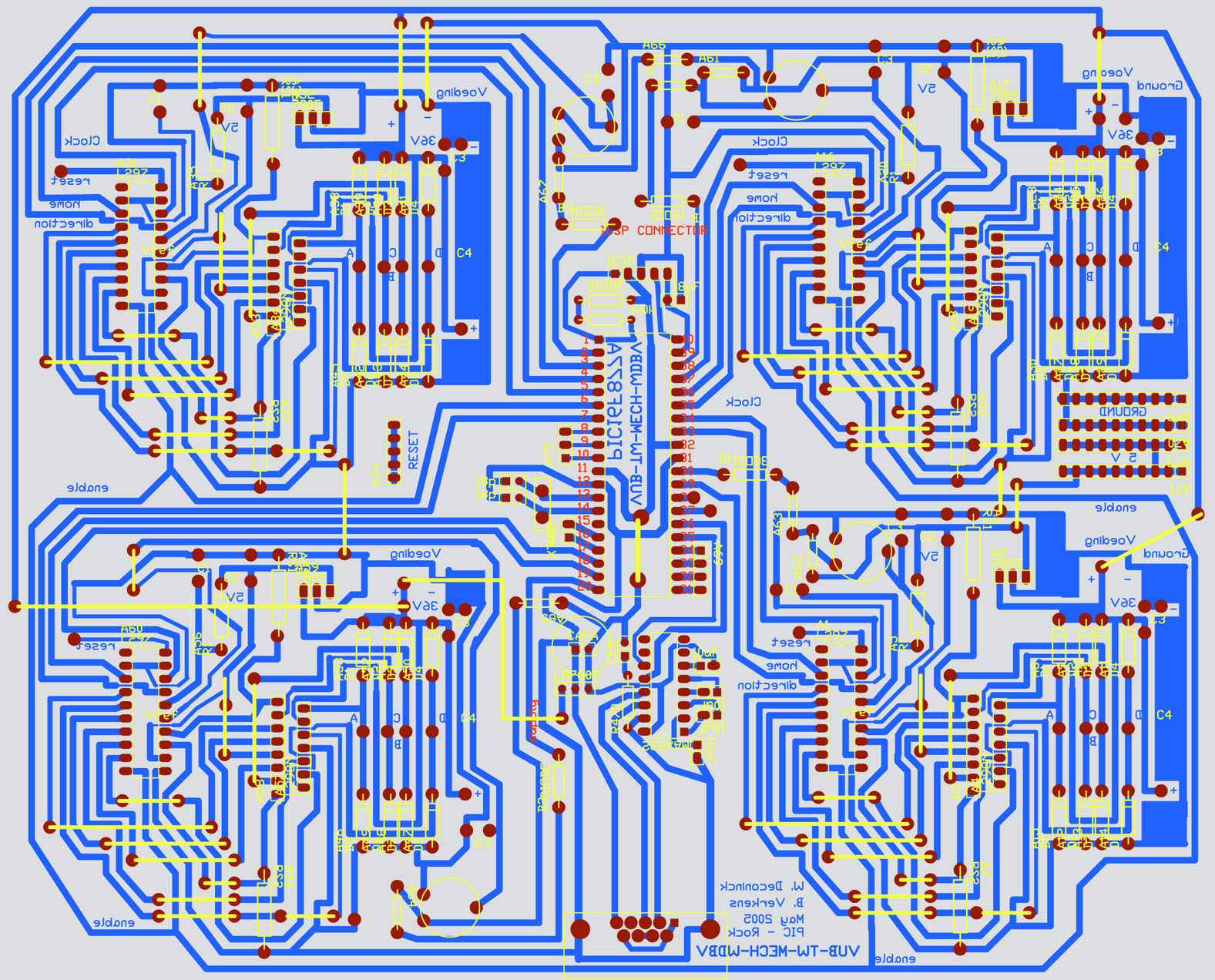
The TraxMaker design of the board is given here.
After a LOT of soldering the result is something to be proud of:
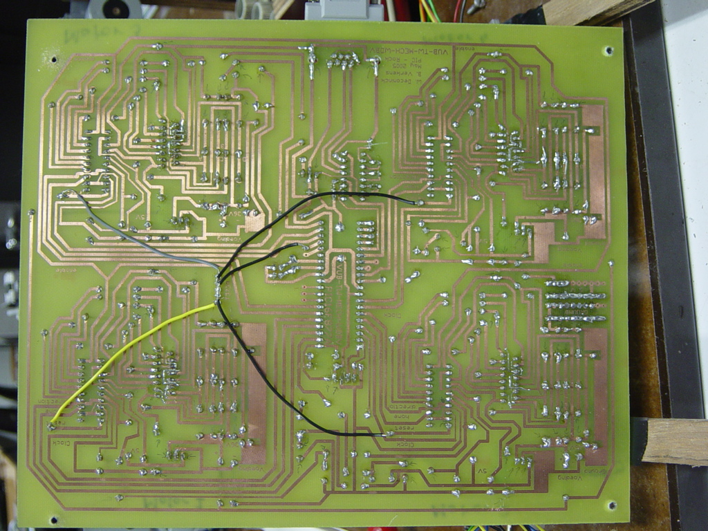
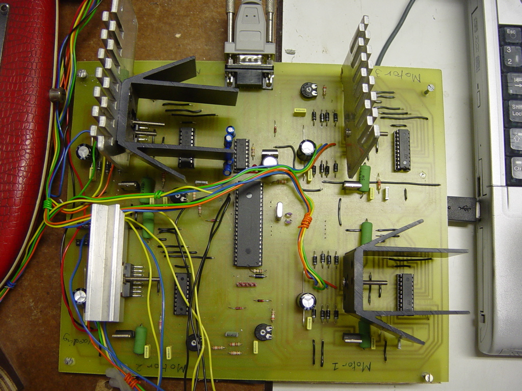

This might look like a huge board, but if u look at the other side u can see
that it really couldn't have been made more compact. At least we tried our
very best to make it as compact as possible. A lot of effort was put in lots
of ways to move "this part" up so that "that part" could be moved a little
closer to "another part" so that the final result would be smaller. What
must also be taken into account is the fact we have 4 big schematics
included: 1 for each motor.
Compare the test-board with our final board and u can see how much we
managed to compress everything together.
Since it's such a big board we double, triple checked all the connections
and we were very pleased to see that the board worked perfectly. No single
error in its design could be detected.
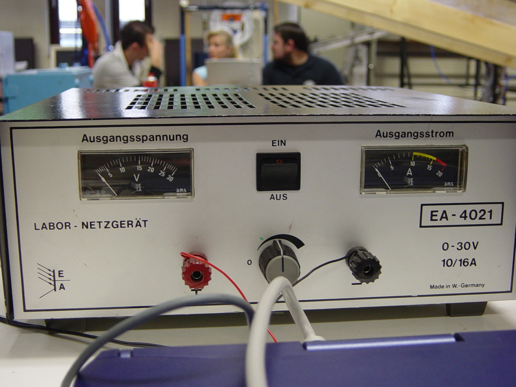
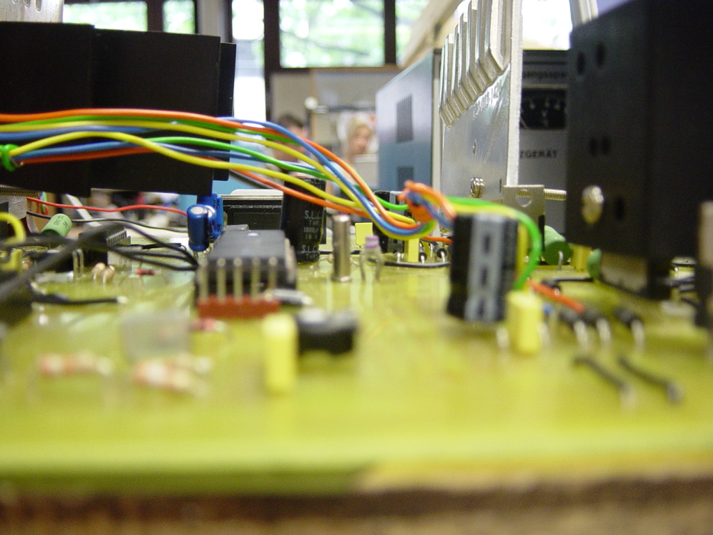
Here is still a picture of our voltage source. Which has to generate 12V and 7A to power all 4 motors.