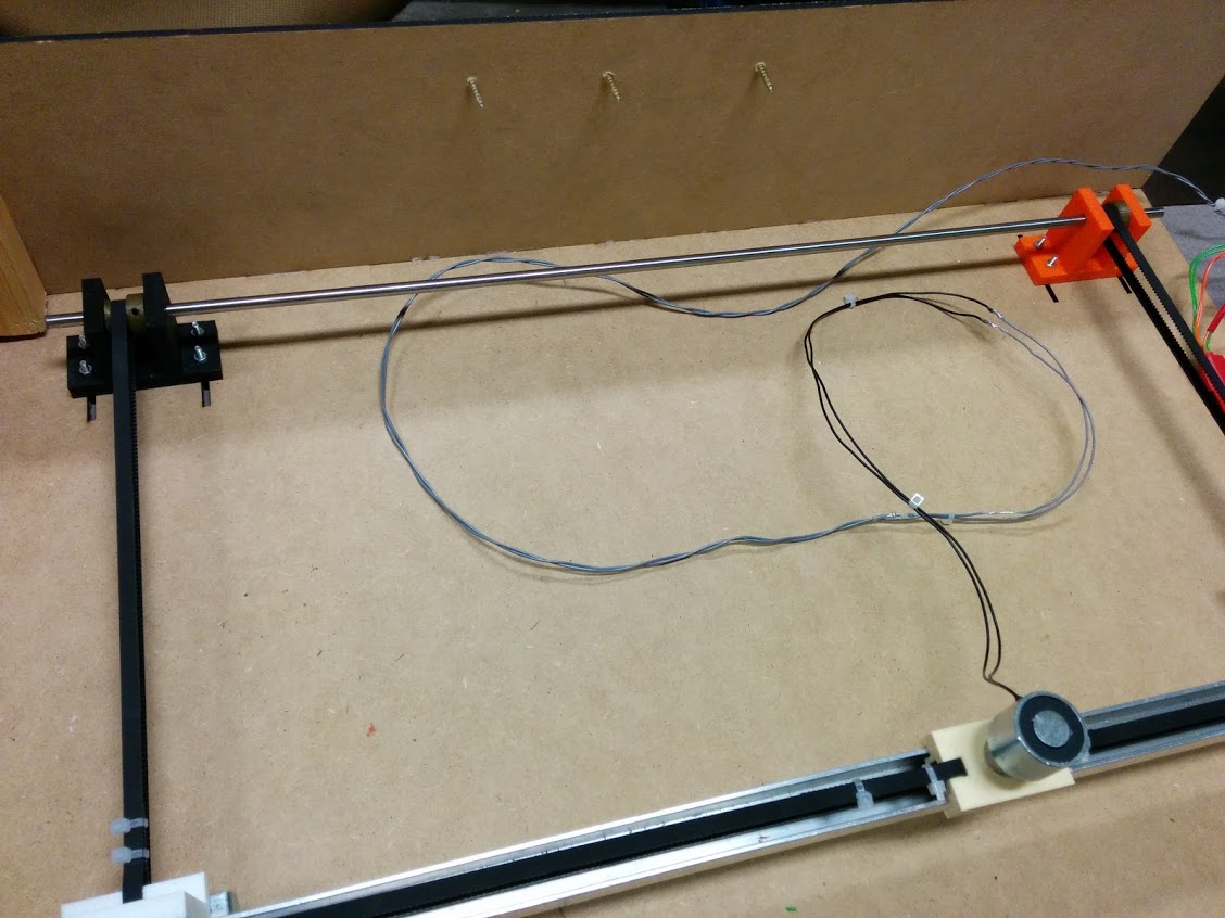
The chess playing robot is a robot able to play against a real player in real time. The pieces are moved automagically from underneath the board using an electromagnet, which is moved around the board with an XY table.
There are different ways to move the pieces from one position to the other, it can either be done using a robotic arm or an XY table mechanism (either from above like a CNC milling machine or from below, meaning underneath the chess board). Although the use of a robotic arm would theoretically allow the integration of the camera into its mechanism, the bad viewing angle as well as the more complex mechanism of a robotic arm pushed the team towards choosing the the XY mechanism. A XY table like mechanism underneath the chess board, gives the player more space to move his own pieces to the different positions compared to the other alternative (the pertruding camera would not hinder much the player's movement). However, this solution requires to design special chess pieces which allow to accomodate the permanent magnets used to move the different pieces by means of an electromagnet controlled by the Arduino.
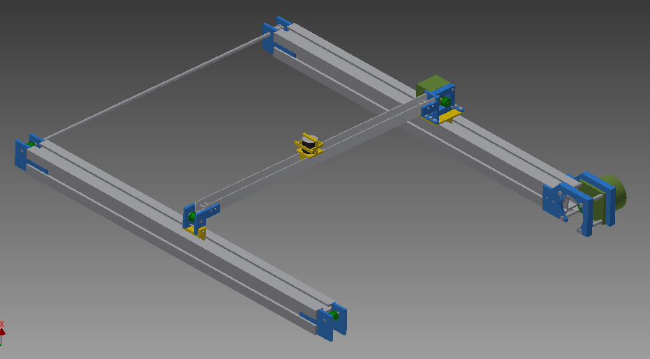
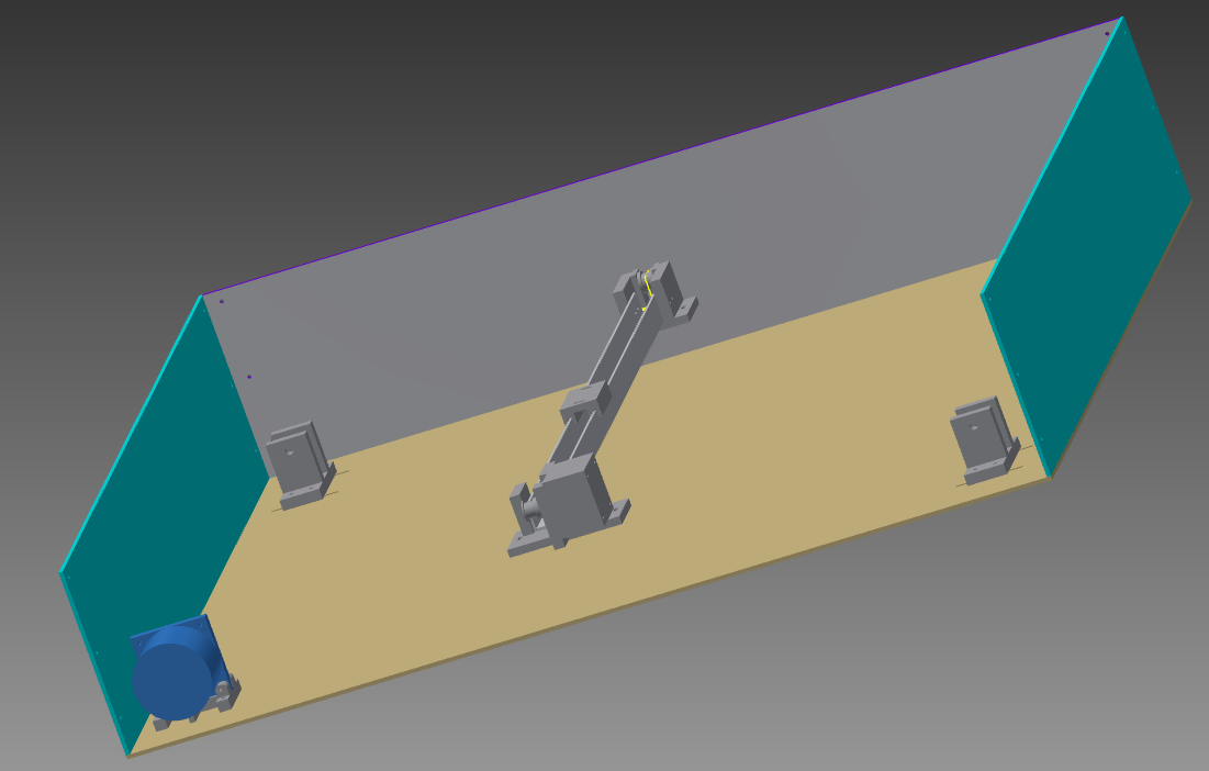
The initial idea was to use 2 aluminium stuts (RS-Components) and a U-shaped beam as guides for the different parts. An early CAD design can be seen on the figure below. The magnet could slide on the U-beam whereas the second motor connected to this beam could slide in the struts thus creating the xy motion. The sliding will happen by belts, driven by two or three motors, that are attached to some sliders that can move across the bars. For the magnet we thought of a system to lock it inside a sort of cage. Unfortunately, this mechanism could not be used, as it would have been to expensive due to the aluminium struts. An alternative solution had to be found
The implemented mechanism does not use the aluminium struts but instead uses only the belts. Two stepper motors are used in order to move them and with them the associated parts, namely the magnet and one of the stepper motors. Using the two parts shown below it was possible to connect the stepper motor and the magnet to the belt.
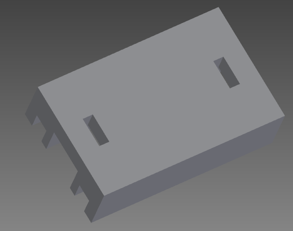
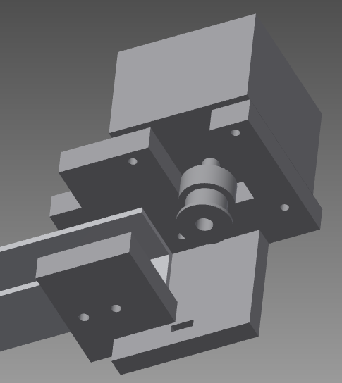
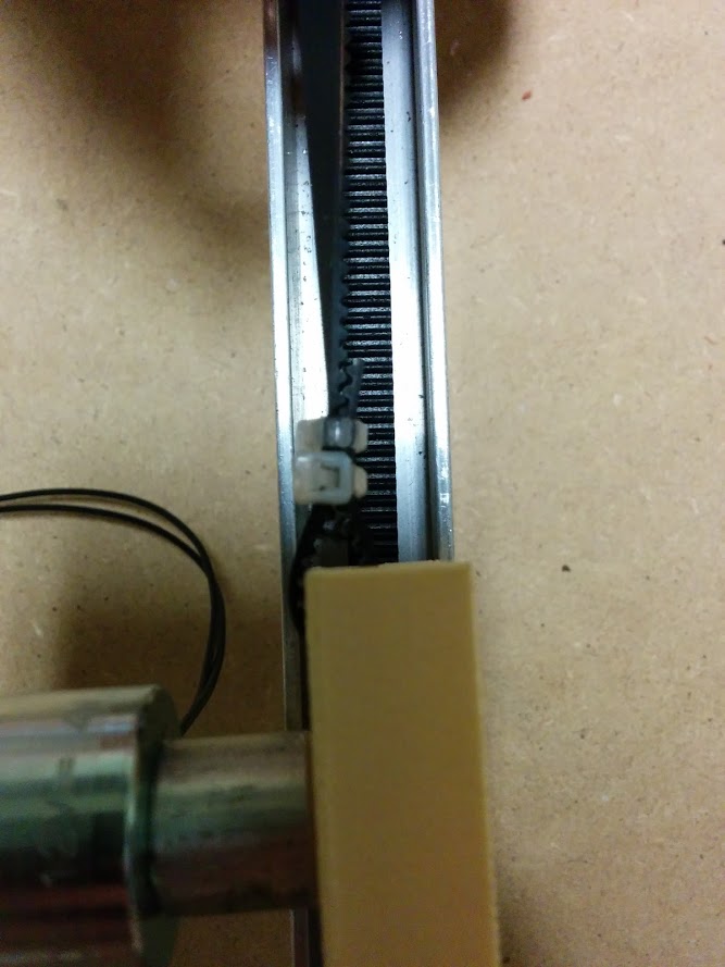
The figure on the left shows the piece on which the magnet is mounted. Note that, this part was modified later on by drilling a hole in the center (otherwise this part would not be 3D printable). This allowed to fasten the magnet on this part using a screw. The part on the right figure shows the part on which the stepper motor would be fixed as well as the U shaped beam. The belt is fixed to both parts by means of the rectangular holes which can be seen on both figures. The belt is guided through the holes and then fastened using tie-wraps as can be seen on the photo below. This mechanism is extremely useful as it allows to pre-tension the belt during the assembly.
Finally in order to "synchronise" the two parallel belts, a shaft was mounted at one extremity which would transmit the rotation of one belt to the other. This can be seen in the photograph below. The shaft is connected to the pulleys using a screw. During the first tests, this seamed to give satisfactory results but eventually the screw screw would loosen itself and consequently the two belts no longer moved in the same way causing the U-beam to tilt. To overcome this problem, a small bore was drilled into the shaft which prevents the relative motion between the screw and the shaft.
The final CAD design can be seen on the figure below. Note that the belt is not represented. The XY mechanism is fixed on a wooden plate (cut by lasercutting) by means of screws. The side walls are glued on the wooden support plate. 6 screws were inserted into the side plates such that the chess board can rest on top of them.
For the construction of the playing board, we needed a thin and strong material. Thin because the pions should be in the range of the magnet and strong because the board should not bend too much under his weight. It must also be flat so the pions find no obstacles when sliding to an other square. One of our additional goals was putting LEDs in each corner of the scares to show the movements, see Electronics.
The best solution for us was using a plastic plate which was completely transparant. Underneath would come a paper made board of the white and black squares, so that you could see it through the plate. Then we needed holes in the plate where the LEDs would come. The first thought was to drill the holes not all the way through, so that surface would remain smooth for the pions, but that seemed nearly impossible in the thin plate. Instaed we made them go through.
We chose the diameter to be a little smaller than the measured diameter of a standard LED. In this way the LED will be clamped into the hole, so we will not need glue. It will also not be displaced by the magnetic forces when it fits really thight. Moreover, the problem of the uneven surface would not be significant: their diameter is after all much smaller than the diameter of the pions.
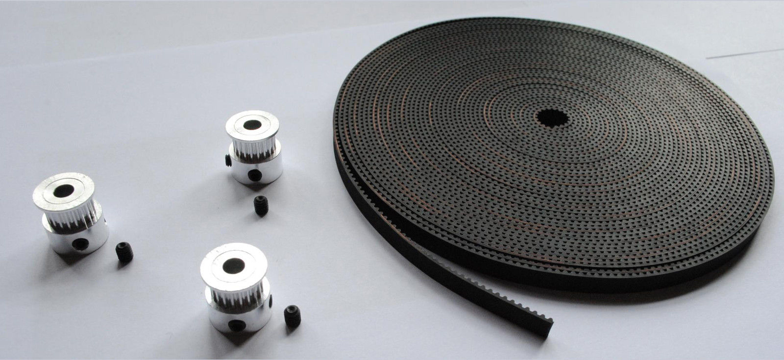
The type of pulleys used would depend on the type of timing-belt used. The main requirement for the timing belts is a sufficient length. Two of the main timing belt types, for small scale mechanical constructions, available on the market are MXL timing belts and GL2 timing belts. Those types two have different properties concerning the teeth’s and thus corresponding pulleys. On the sites of RS components and Farnell only MXL timing belts where available. The ones available on the site had the inconvenience to be closed small timing belts. This is why we decided to use GL2 timing belts that can be bought on the internet on sites like EBAY for a much better price and on the wanted length. GL2 timing belts are the ones that are mainly used on Reprap 3D printers.
A timing belt of 5m was thus ordered and was delivered with 3 pulleys with a bore of 5mm.
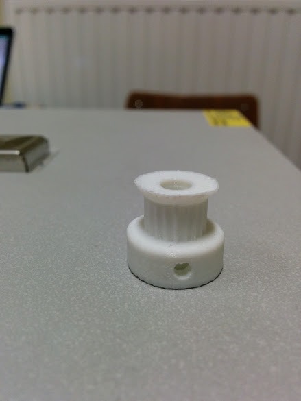
The total amount of pulleys needed for the project (see design) is of 6. Because the pulleys made out of metal are expensive and because they would take a lot of time to be delivered (GL2 pulleys not available on RS and Farnell). We decided to print the missing pulleys ourselves. The metal ones will be used on the motors. (The bore of one of the metal pulleys had to be increased to fit on the shaft of the biggest stepper motor)
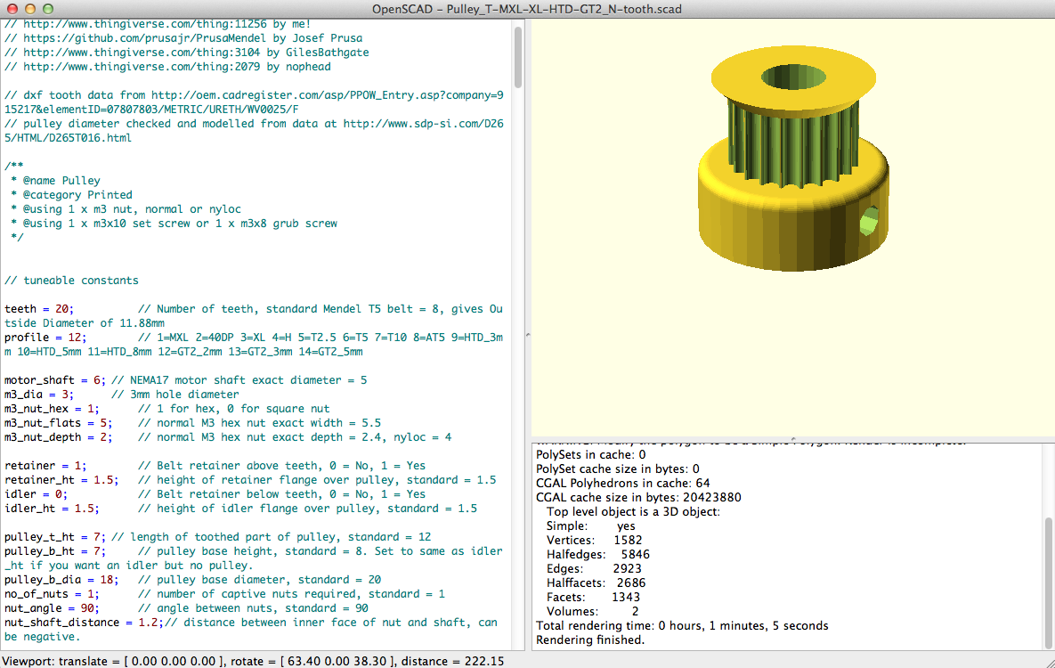
The CAD design of the pulleys has been found on the site: Thingiverse. The site contains a link to a OPENSCAD script It also that enables to generate the right pulley with all the needed parameters (like the number of teeth depth, extra depth for printing and so on)
The FABLAB is a place that has a certain amount of professional tools, printers, 3D printers and Laser-cutters. It is open to Erasums-hogeschool and VUB students on Wednesday afternoon and on Thursdays afternoon. In order to be allowed to use certain machinery tutorials must be followed while guided by supervisors of the FABLAB. Those tutorials can only be followed on Thursdays.
Types of 3D printers used:
The replactor 2 prints in PLA while the replicator 2X prints un ABS. While ABS is toxic and PLA not, it is much stronger. Because nearly all the pieces are under tension in our project we tried to print as much as possible in ABS using the replicator 2X printer. Unfortunately, the number of printers being limited (and only one replicator 2X working properly) and certain pieces taking more than 2 hours to print, we had to use replicator 2 printers that print in PLA. The ultimaker has been used to print some pieces but those were defective due to a bad configuration of the printer (the ultimaker printed in PLA).
Types of Laser-cutters used: CYBORG 1080 LASERCUTTER 60W
When cutting the wood pieces for our project we encountered some issues. First one need to know that the laser cutter uses a lens in order to focus the laser-beam and that mirrors are also used for the laser to be able to move all over the place. As a result when when cutting pieces far away from the laser souce the laser is not as powerful. During the introduction to the machine we were told to do a small test in the corner to see if the settings of the laser are correct. However the instructor didn't tell us that in the case of bigger parts this test should be carried out where the laser is the weakest (probably because he assumed that the parts which we were going to print were small). Due to the approaching deadline, the time was not enough to recut the parts and consequently they had to be cut out using a cutter which explains the small imperfections in our parts.
A clip of the final assembly can be seen below. Note that due to the weight of the motor, the belt was deflected downwards. As a consequence the motors had to produce more torque in order to make the mechanism work. To overcome this issue, two wheels were attached to the concerned parts using adhesive tape. This can be seen on the picture of the final assembly. Unfortanatly the Leds were removed, the reason for this is that the the magnet is not strong enough and it has to be put close to the chess board leaving no space for the LEDs.
To control the movement of the chess pieces, stepper motors and an electromagnet is needed. To make the chess game more interactive and to increase the level of attractivity the robot, electronics like LEDs and an LCD-screen are used.
For our application the needed motors had to answer to a certain amount of requirements:
Stepper-motors are the motors that answer all the requirements listed above. This is thus the type of motor that has been chosen for this project.
For this project recycled stepper motors where used. Unfortunately no datasheets on those motors where given with those motors and they couldn’t be found on the internet. The only information that was given is the maximum current they allow.
In order to know how to wire the motor tests first needed to be done. The two motors are 6 wire motors. Those motors can either be half or full wired in a circuit.
In order to know what wires correspond to one same phase, a multi-meter was used to measure the resistance between the different wires.
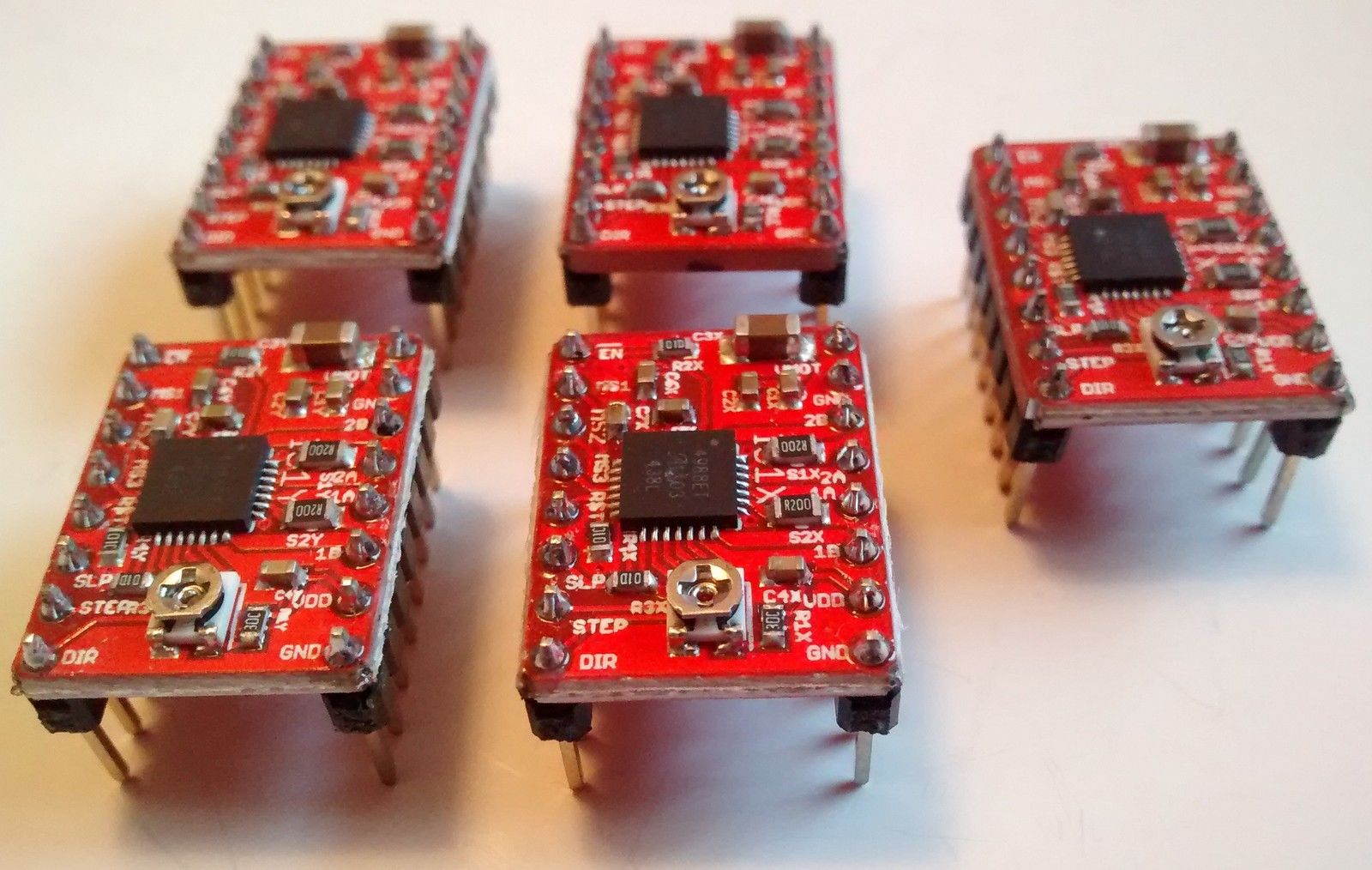
The control of the stepper motors can be done thanks to H-bridges. Stepper-driver chips integrate those h-bridges in an efficient way. Often those stepper-driver chips are mounted on stepper drivers in such a way that they are easier to use and to install. (Stepper-driver ships are small and need precise soldering) For our application we asked if we could use one of the stepper-drivers available on the market: pololu a4988
The extra advantages of that driver are the availability of:
Because of the size of the chessboard and the fact that we don’t need a very high precision the last point won’t be used in this project.
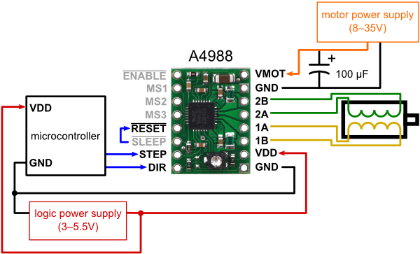
The scheme used for the pololu is the following
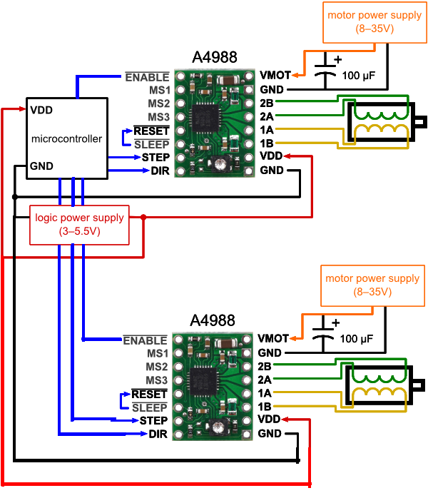
In order to reduce the amount of energy used we will use an extra pin on the pololu: ENABLE. The ENABLE pin enables us to put the motor in sleep mode. Indeed in normal use, unless asked otherwise, a stepper motor will keep it’s current position by keeping current in certain coils. In our application that happens in a horizontal plane this “particularity” of stepper motor is not required. The scheme thus becomes (whith two pololus = two motors) :
Before the pololus where ordered on internet, one got lend to the group by an assistant. This enbabled us to test the wirering of the pololus and check what motors worked fine. The following code shows how to control the motors using the pololus and shows the code used to test the motors (parameters are changed in function of what we want to test):
To move the chess pions, permanent magnets are glued at the bottom of the chess pions and an electromagnet is placed on the moving XY-table. The latter has to be an electromagnet, because it has to be “ON” when it has to move a chess piece, else it has to be “OFF”.
Neodymium magnets are used for the permanent magnets at the bottom of the chess pieces. These are difficult to demagnetize and are not easily affected by heat, which comes from all the electronics in the box.
Because of the fact stable attraction and smooth movements of the pieces are required, DC powered electromagnets are preferred. The most efficient way to achieve this is to use the same shape for both magnets. The chess pieces have round bottoms, so in this case round magnets are used.
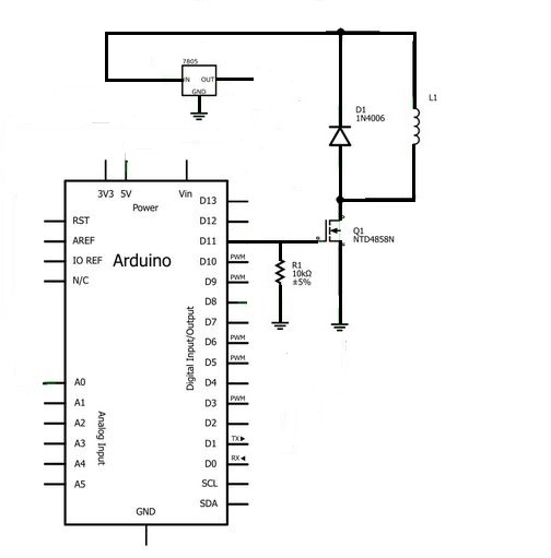
In the schematic below, you can see an I/O Arduino pin connected with the N-Channel Enhancement-mode MOSFET, which is connected to a parallel circuit of the protection diode and the electromagnet.
When the Arduino pin gives 0V, G=0V, the MOSFET will work as an open switch. When the Arduino pin gives 5V, G=5V, the MOSFET will work as a closed switch. So, with this type of MOSFET there will only flow a drain current when the voltage applied on the gate is positive.
The advantage of the MOSFET is that it will not draw a gate current, not even a leakage current. A disadvantage is that the thin layer of glass cannot withstand much voltage, even with a static charge, whereby it can be destroyed.
The MOSFET has to be mounted in a circuit that will drain off the charge, so we will use a pull-down resistor.
The current that flows through the coil (DC electromagnet) creates a magnetic field. This magnetic field will collapse suddenly when the current is switched off, whereby there will be a brief high voltage across the coil which can damage the MOSFET.
A protection diode allows the induced voltage to drive a brief current through the coil and diode, so the magnetic field dies away quickly rather than instantly. This prevents that the induced voltage will become high enough to cause damage to the MOSFET.
The chosen DC electromagnet needs a voltage supply of 12V, but the other electronics like shift registers and the Arduino work on 5V, so we need a 7805 voltage regulator.
The goal is to light up the trajectory a pion follows. This could be helpful for elderly people who forgot there or the opponent’s last move. This extra makes the chess playing robot more attractive.
Technically this can be accomplished by lighting up the four LEDs at every square corner. To light up the trajectory, a for loop over all the squares can be implemented in the Arduino.
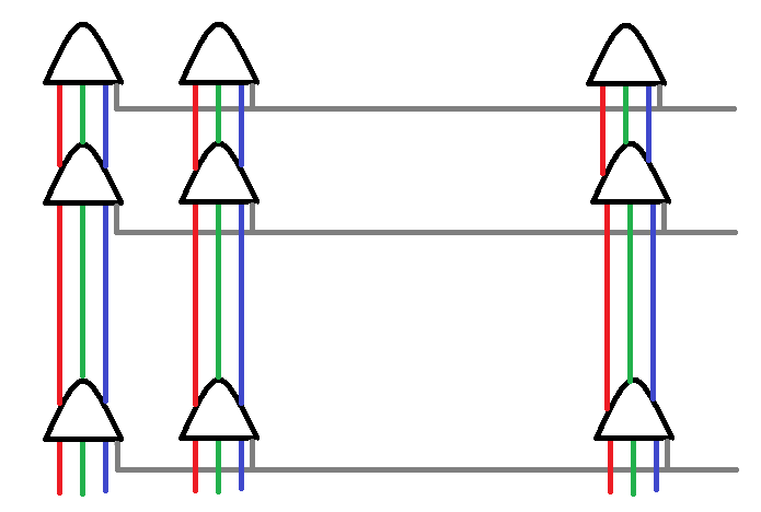
The working principle is visible in the following figure of the RGB LED matrix:
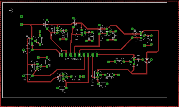
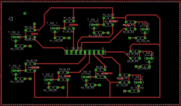
The whole explanation discussed below can be followed in the figures of the PCB (Eagle) schematics.
The anodes of the LEDs are connected for every row and the red, green or blue cathodes are connected per column. By selecting only two neighbour rows and only two neighbour columns of a certain colour, this will automatically light up a square of LEDs in that colour. Selecting means in this case, lighting up the LED which is equivalent to a low voltage on the cathode and a high voltage on the anode.
Of course, current limiting resistors are needed to prevent damaging of the LEDs. As can be seen in the scheme, for every column of cathodes a current limiting resistor was calculated in order to light up one square of LEDs at a time.
In this case, there are 81 LEDs (LED matrix has 9 rows and 9 columns), so shift registers (serial input, parallel output) are used in between the Arduino and the LED-circuit to achieve more outputs. To power the LEDs, electronic switching circuits in the form of simple transistors are used in between the control output of the shift register and the anode or cathode of the LED. The power is provided by the voltage regulator.
Bipolar junction transistors are used instead of MOSFETs, because they are a lot cheaper. On the other hand, by using MOSFETs we would get rid of all concerns about drive current, which leads to an easier design.
NPN-transistors were chosen. To light an LED, the Arduino outputs 5V to the base of the anode transistor, whereby a current can flow from the collector to the emitter to put the anode on 5V. At the same time, the Arduino outputs 5V to the base of the cathode transistor. This puts the cathode on a low voltage equal to the 5V minus the forwards voltage of the LED.
If we should have used RGB LEDs, then we needed 36 transistors (9 rows of anodes and 27 columns of cathodes) and five 8-bit shift registers to control these 36 outputs. To reduce the cost and the time to make the PCB and doing the soldering, simple red LEDs are used. As a result, the final design was kept for the red LEDs thereby it became more conservative. In this case 18 transistors (9 rows of anodes and 9 columns cathodes) are needed and three 8-bit shift registers.
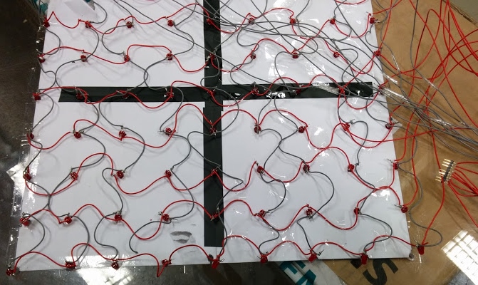
The grey wires are the connections for the cathodes and the red wires the connections for the anodes.
The results of the chess move visualizing LEDs are visible below:
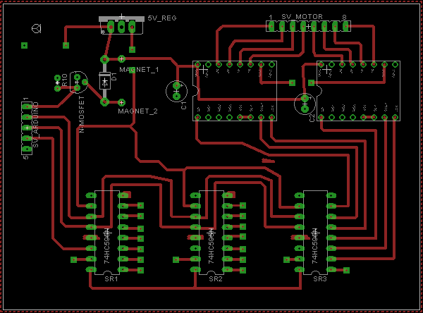
To make the PCB, the software “Eagle” was used. The goal was to make one PCB, but due to the fact that there were too many components and connections, it had to be a two-layered PCB, whereby the PCB became too chaotic and too difficult to solder. That’s the reason why we split the electronics over three PCBs.
In this schematic, you can see the structure of the three PCBs.
The first or the main PCB is the one which is powered by the 12V source and where the outputs of Arduino arrive. One of these Arduino signals goes to the MOSFET and in this way to the electromagnet, the other signals go to the shift registers. The shift registers are powered with 5V coming from the voltage regulator and are connected with the other two PCBs and with the motor drives, which output is connected with the motors.
In the second PCB, the inputs are the outputs of the shift registers of the first PCB and the outputs are the connections to the anodes of the LEDs. The 5V supply and the ground come from the first PCB.
The third PCB is similar to the second, but in this case it is connected to the cathodes instead of the anodes of the LEDs.
Not all the connections could be made on Eagle itself and had to be made afterwards manually with wires.
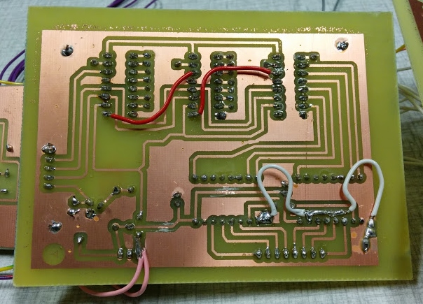
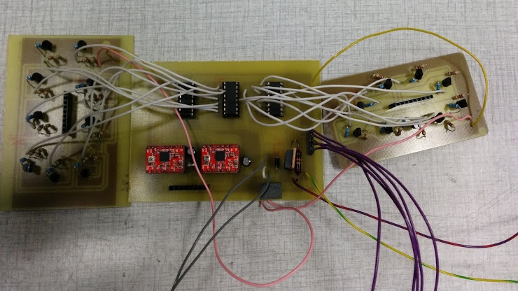
In the figure below, you can see the bottom of the main PCB. The white wires are ground connections and the pink wires are the 5V connections. The aim of the two red wires is to set the three shift registers in cascade: connection between pin 9 of SR1 and pin 14 of SR2 and between pin 9 of SR2 and pin 14 of SR3. On this picture, a green wire is missing which is the connection of the 5V with the Vcc of the shift registers.
On top of this PCB there are 18 white wires: nine of them are going to the anode PCB, the other nine are going to the cathode PCB. The five purple wires are connected to the Arduino: GND, serial, latch, clock and an I/O pin for the data of the magnet. The two yellow wires connect the anode and cathode PCB with the ground of the main PCB. The yellow/green wire is the connection with the ground of the source and the red/purple wire is the connection with the 12V of the source.
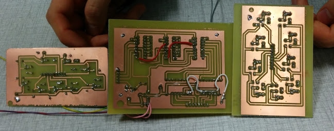
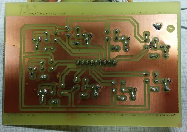
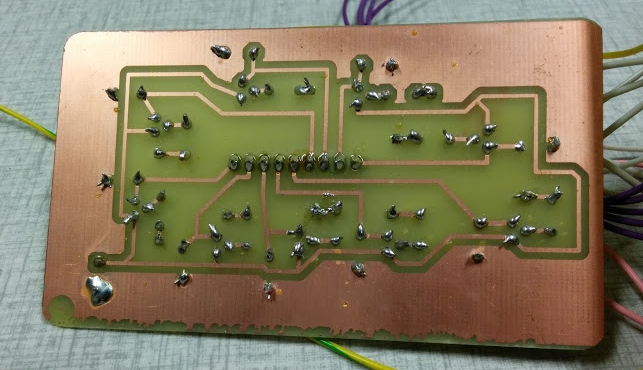
Nine red wires are connected to the top of the anode PCB and nine grey wires are connected to the top of the cathode PCB, these are the connections with the LED grid. The bottom of the anode and cathode PCB can be seen in the figures below.
Once the components were soldered on the board, the PCBs were tested. First we wanted to test if the motors worked, unfortunately this was not the case. After various attempts of finding the error, we figured out that the Vcc of the shift registors were not connected to the 5V. This error was found too late, thus it was decided to not use the PCB but use a breadboard instead for the electromagnet and motors. This allowed to have at least a functioning prototype of the chessboard.
However, the PCBs worked when the missing connection was soldered. At the end, the LEDs were lighted by the PCBs, so we could say that – although there was a lot of soldering work - everything worked fine and was well soldered!
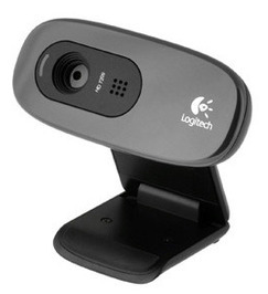
When the player has made his move, it is time for the robot to analyze the board. The position of each piece has to be found. In order to achieve this, the robot has a webcam linked to a computer. After taking a picture with the webcam, the computer has to process it. This is done by a Python script. Here is the webcam used:
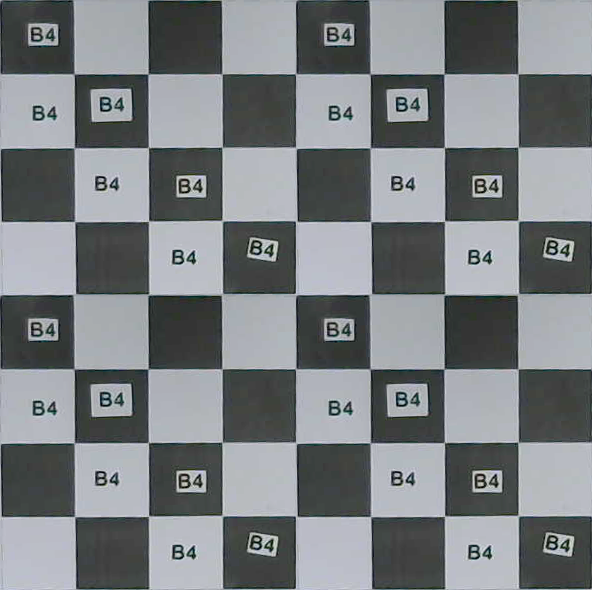
The first step is to crop the picture so that it only contains the board. The image is then cutted in 64 parts (corresponding to the 64 squares), which are analyzed using an OCR script (Optical character recognition). Normally at this point, all the pieces and their positions are well known.
Here is a picture of the board taken by the webcam, after being cropped.
The cutting of the image is easily done with the PIL package : imageCutter.py
Here is the result:
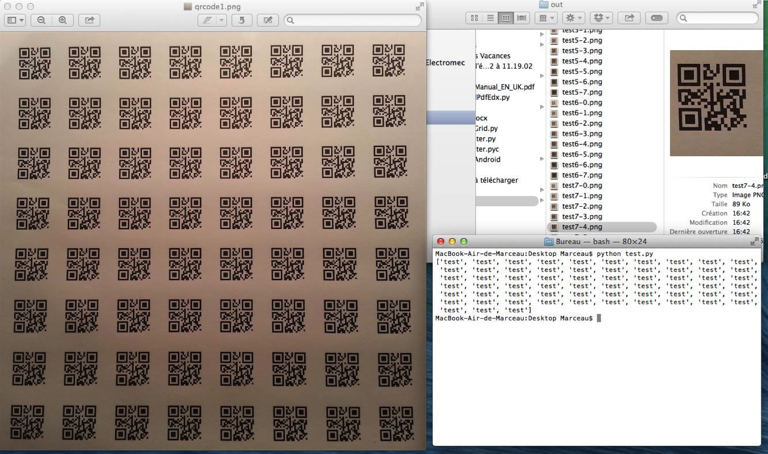
At first, we tried to use some QR-code recognition algorithm to distinguish the pieces. Everything was working perfectly when using QR-codes big enough, but when trying to see all the table and recognize the QR-codes, the resolution of the webcam was not good enough. Indeed, the pieces needed to be able to pass between two other pieces, when moving. The QR-codes could then not be bigger than half the size of the squares.
The code we used is based on the zbarimg module. You can see it here : parser.py
To solve the problem of the webcam resolution, we tried to use an OCR algorithm. We tried to make the Tesseract algorithm working in the same conditions. Luckily, it can detect the pieces when the webcam is seeing all the table, the resolution is good enough. You can see it here : parserTesseract.py
However, the black cases caused some problem for the Tesseract algorithm. It could not recognize it with the black box, when the same image was recognized if the black box was removed. The solution was found by using OpenCV. The first image resulting of the cutting is automatically cropped if there is a black box, even if the paper (with the text) is not at the center of the case. You can see it here : unbox.py
=> =>It is done by automatically finding the contour between the black region and the white region, then stabilize if needed (so that the text is horizontal), then cropping to keep only the white region.
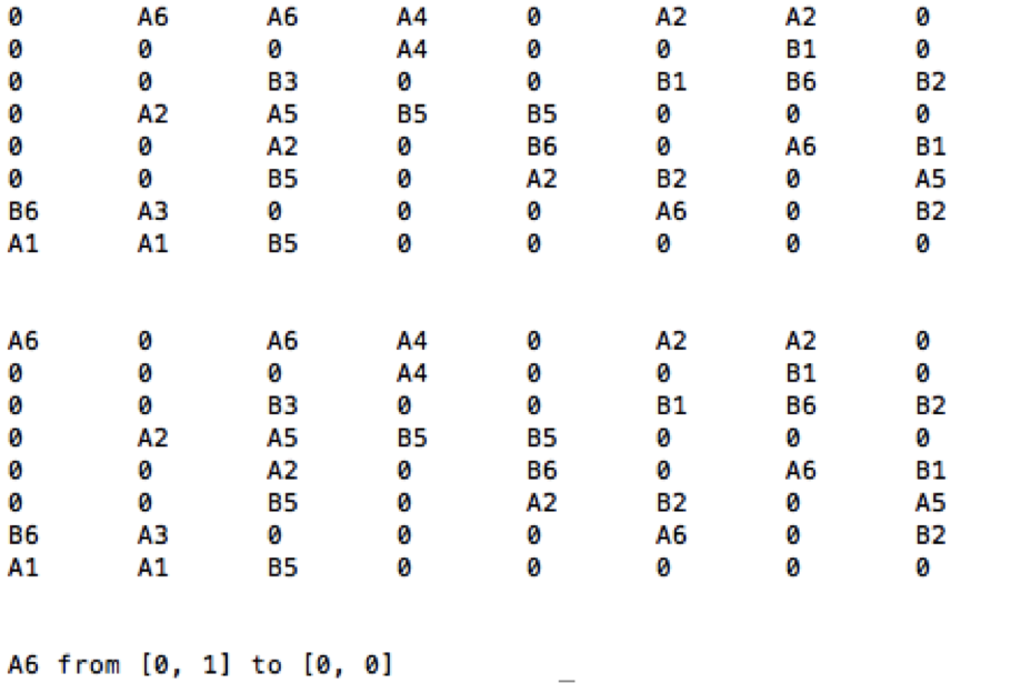
When all the cases have passed through the OCR recognition, the algorithm can then compute the move made. Then, this information is sent to the artificial intelligence.
The Python codes are available on this Github repository.
Since the goal of this project was not to program an arificial intelligence, a suitable one had to be found on the internet. Of course attention had to be paid that the artificial intelligence was open source allowing us to modify it to our needs. A few chess engines can be found below
In the end, Sunfish was chosen mainly for the following two reasons:
The way Sunfish works is the following. Each piece posses a certain value depending on its position on the board. The white pieces (i.e those controlled by the user) are assigned a negative value while the black one are counted positively. An overall score is calculated by taking the sum of all those values. The next move is simulated as well as the next move of the player and so on (how far the engine goes can be defined by a variable). Once everything was simulated the chosen move will be the one which will corresponds to the one resulting after so many iterations to the highest overall score.
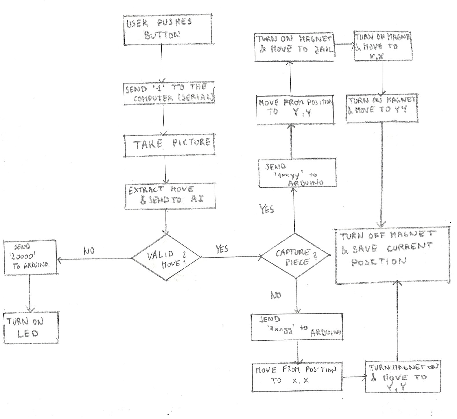
Taking this into account, the procudure is the following. The user makes his move and once it is done, a push button is pressed. The arduino will then send a byte to the Python Code using PySerial. In the Python script, if the recieved byte matches to the predifined one, the users move is decodes using the technique presented in the Visual Recognition section. The move is then decoded such that the artificial intelligence is ablt to interpret the move (f.eg 'a1a2'). The chess engine will then return the move of the computer in the same format (i.e. 'a1a2'). This is then encoded to a string containing 5 characters. The fist one is either '0' (simple move from A to B), '1' (move from A to B but the piece at B is going to jail) or '2' (invalid move). The next characters represent the coordinates of A and B (two characters for both) in a cartesian coordinate system. When the first character is '2' the, arduino will ignore the next 4 characters. This is summarized in the schematic below.
The movements of the motors were tested by sending the the string via the Arduino Serial Monitor, as when writing this page, some minor components still have to be implemented. A video of the movement can be seen in the video below. Note that since the knight is able to pass obove the pieces a deviation procedure was implemented causing the pieces to move along the border of the cases (for simplicity it was implemented for all the pieces).
The other videos of the robot are available on YouTube.
Here you can find the code for the move visualizing LEDs
/** * Serial communication between the Arduino and the * computer running python. (see other code) * * The arduino sends a '1' to tell the computer when the * user has done his move. PC makes what he has to do and * sends 4 charachers through the serial port. With that * the arduino moves the motors such that the piece is * moved. */ //======================================================== // Includes //======================================================== #include <LiquidCrystal.h> //======================================================== // Pin Definitions //======================================================== #define LED 13 #define LCD_BUTTON 0 #define MOVE_MADE '1' #define MOVE_UNDO '2' #define INVALID_MOVE "3" /* The following macros are needed in order to allow the pc play a sound when its pions are moving The arduino sends either MOCE_DONE or DOING_MOVE so that the PC is synchronized with the arduino and only plays a sound when the piece is actually moving or not */ #define MOVE_DONE '4' #define DOING_MOVE '5' int dataPin = 12; //Serial Output to Shift Register int latchPin = 11; //Shift Register Latch Pin int clockPin = 10; //Shift Register Clock Pin // not sure about these pin numbers int magnetPin = 2; // arduino pin for the electromagnet //======================================================== // variables //======================================================== //boolean moveReceived = false; boolean moveReceived = true; // just to test long t = 0; int analog; String nextMove = ""; String prevMove = ""; String data; int dir[2]; LiquidCrystal lcd(8, 9, 4, 5, 6, 7); //Associtae PINS to LCD // globally defined array size int array_size; //way to do it: http://arduino.stackexchange.com/questions/3774/how-can-i-declare-an-array-of-variable-size-globally int arrayTrajectory[16]={ 0,0,0,0,0,0,0,0,0,0,0,0,0,0,0,0}; // max 8 steps on a location with a certain row and column number: 8x2=16 // introduce offsets because shift registers are cascaded as: arduino - anode (24-16) - cathode (15-7) - motors (6-1) and their corresponding numbers int SR2Offset=8; // the first 8 bits that will be shifted into the shift registers int SR3Offset=SR2Offset+8; int cathodeOffset=6; int anodeOffset=15; unsigned long timer1;//StepTrajectory; // "ALWAYS use unsigned long for timers, not int" unsigned long timer2;//timer2Move2BeginPos; // // maybe even make another for diagonal trajectoy (will take longer because of longer distance) int index=-1; // corresponds to the (number of moves)*2 that have been completed of the desired trajectory int time1Step=10000UL; // in milliseconds, to go with motors from 1 square to the next, assume 1 second= 1000ms // begin step= 10s= 10000ms //the "UL" after the number is a syntax detail that is important when //dealing with large numbers in millis and micros void setup() { Serial.begin(9600); pinMode(LED,OUTPUT); /* just so I have enough time to lauch the python script to communicate arduino will wait 20 sec */ //delay(20000); pinMode(dataPin, OUTPUT); pinMode(latchPin, OUTPUT); pinMode(clockPin, OUTPUT); pinMode(magnetPin, OUTPUT); // int myTest1[8]={1,2,3,4,5,6,0,0}; // 8 , 1-8 // valueShiftOut(myTest1); // int myTest2[8]={9,10,0,0,0,0,0,0}; //3 , 9-16 // valueShiftOut(myTest2); // int myTest3[8]={17,18,0,0,0,0,0,0};//2 , 17, 24 // valueShiftOut(myTest3); digitalWrite(latchPin,LOW); } void loop() { // TESTS: // digitalWrite(latchPin,LOW); // int myTest1[8]={1,2,3,4,5,6,7,8}; // 8 , 1-8 // valueShiftOut(myTest1); // int myTest2[8]={0,0,0,0,0,0,0,16}; //3 , 9-16 // valueShiftOut(myTest2); // int myTest3[8]={17,0,0,0,0,0,0,0};//2 , 17, 24 // valueShiftOut(myTest3); // digitalWrite(latchPin,HIGH); // Trajectories: int myPositions1[4]={ 8,8,1,1 }; // just to test, have to convert strng nextMove to an array of 4. int myPositions2[4]={ 4,1,4,8 }; int myPositions3[4]={ 4,5,6,6 }; if (moveReceived) { // To Be executed when move has been received //reconstruct total trajectory: int trajectoryLength=trajectory(myPositions1,arrayTrajectory); // only usefull length (without from all the 0s) Serial.println(trajectoryLength); // Serial.println("BEGIN"); // for (int i=0; i < 8; i++){ // Serial.println(arrayTrajectory[i]); // } // Serial.println("END"); if(index==-1){ // so a move is received, but not started yet // go with motor to the begin position (motor can be far away from place), wait long enough, so we can start the trajectory afterwards where motor and LEDS are synchronous (moving at same location and same speed) //delay(10000); not got to use, we use another timer for it! otherwise we can't do other things like displays on LCD timer2=millis(); // start time of moving from initial pos towards begin pos in trajectory/array index=0;// we will soon arrive at begin pos of array, next loop, we get in the enxt if statement if time has passed to get there // !write here the code to really move to begin pos of array with the motors: use time for 1 step, use number of steps to do String string4 = "we now start to move from an arbitrary pos to the first pos of the trajectory"; Serial.println(string4); //Serial.println(timer2); movePiece1Step(index); } if(((millis()-timer2)>7000UL)&&index==0){ // change timing depding on time needed for 1 step and multiply by the number of steps you need //we can start the first move: going from begin pos to second pos in array, here we ligh up the first square as long as pion didn't reach second square String string3 = "we now start the first move of the trajectory"; Serial.println(string3); index=2; //when move is done and when we arrive at begin pos of the array, we can start next move in array movePiece1Step(index); //keeps moving/lighting untill you ask for a second move timer1=millis(); // starting time of first move in array digitalWrite(latchPin,HIGH); } if(((millis()-timer1)>3000UL*index/2)&&index>1){ //index=2 ==> 5s, index=5 ==> 10s, index=6==> 15s index=index+2; movePiece1Step(index); //keeps moving/lighting untill you ask for a next move String stringOne = "ith step of trajectory has been completed"; String stringindex = String(index); //Serial.println(stringOne); //Serial.println(stringindex); digitalWrite(latchPin,HIGH); } // String string2 = String(index); // Serial.println(string2); // if(index>trajectoryLength-1){ // all moves in trajectory are completed // for( // digitalWrite(latchPin,LOW); // index=-1; //when move is done and when we arrive at begin pos of the array // moveReceived = false; // this can maybe go away after test // String string2 = "trajectory is finished"; // Serial.println(string2); // } } } //========================================================== // Helper functions/methods //========================================================== void movePiece1Step(int index) { // if only motors/ leds give extra boolean as input :-) also add magnet boolean to determine if magnet is needed or not (it is needed if it is doing trajectory movement, not for first movement) /* this is the method where we would put the control for the motors to move the piece from nextMove[0:1] to nextMove[2:3]. For now we simply light a the LED */ // TODO : put here code to decode the move so that it can be // interpreted // for sure first 6 motor bits to send // led: int row1=arrayTrajectory[index]+cathodeOffset; int column1=arrayTrajectory[index+1]+anodeOffset; int row2=row1+1; // for the LED square int column2=column1+1; // for the LED square // motor bits (no offset): which have to be turned on? //Serial.println(row1); //Serial.println(column1); int listValues[]={ row1,row2,column1,column2 }; // and motor bits still to add // int arrSize = sizeof( listValues )/ sizeof( int ); // Serial.println(sizeof( listValues )); // Serial.println(sizeof( int )); ===> this doesn't work in for loop... int arrSize =4;// take 4 now because 4 bits for LED, afterwards add motor bits (+6) ==> 10 int indexSR1=0; int indexSR2=0; int indexSR3=0; // could make SR1 max 8, SR2 max 3 (1 anode, 2 cathode), SR3 max 2 (2 anodes) int SR1[8]={ 0,0,0,0,0,0,0,0 }; // Numbers from 1-8, zeros to not have arbitrary values in unfilled places int SR2[8]={ 0,0,0,0,0,0,0,0 }; // Numbers from 9-16, zeros to not have arbitrary values in unfilled places int SR3[8]={ 0,0,0,0,0,0,0,0 }; // Numbers from 17-24, zeros to not have arbitrary values in unfilled places //Serial.println(arrSize); // fill the SR arrays by looking at the corresponding numbers: for(int i=0; i < arrSize; i++){ //Serial.println(i); if((listValues[i]>0)&&(listValues[i]<9)){ SR1[indexSR1]=listValues[i]; indexSR1=indexSR1+1; } else if((listValues[i]>8)&&(listValues[i]<17)){ SR2[indexSR2]=listValues[i]; indexSR2=indexSR2+1; } else if((listValues[i]>16)&&(listValues[i]<25)){ SR3[indexSR3]=listValues[i]; indexSR3=indexSR3+1; } // //neglect the unfilled places } // Serial.println("SR1:"); // for (int i=0; i < 8; i++){ // Serial.println(SR1[i]); // } // // Serial.println("SR2:"); // for (int i=0; i < 8; i++){ // Serial.println(SR2[i]); // } // // Serial.println("SR3:"); // for (int i=0; i < 8; i++){ // Serial.println(SR3[i]); // } // Shift out the values: SR1 first, than SR2, finally SR3 valueShiftOut(SR1); valueShiftOut(SR2); valueShiftOut(SR3); // // Magnet // // LCD shield // //perform the job by latching the bits from the SR: digitalWrite(latchPin,HIGH); // send the desired voltage to the SRs Serial.write(DOING_MOVE); //digitalWrite(LED,HIGH); /* In order to make the undo we have to store the previous move so that we can move the piece back to that position */ //prevMove = nextMove; //store the move so that we can revert Don't do this, we won't have done a total trajectory already (only done 1 step) //back to it } // Calculates the trajectory corresponding to the performed chess piece move. // Inputs is an array where the first 2 values are the rows and columns of the initial position and the next 2 values are the rows and columns of the next position. // The trajectory is dependent on the type of pion and can be deduced with the following if statements. int trajectory(int myPositions[4],int arrayTrajectory[]) { // C++ isn't able to return array, therefore the array is globally defined and manipulated inside this function // begin position int beginRow=myPositions[0]; int beginColumn=myPositions[1]; // end position int endRow=myPositions[2]; int endColumn=myPositions[3]; // result: arrayTrajectory[0]=beginRow; arrayTrajectory[1]=beginColumn; // int arrayTrajectoryLength=(abs(endColumn-beginColumn)+1)*2; // usefull array length. Unusefull part are zeros (length declaration = 16 necessary to global define an array) // Ex for move column: str(1,5,1,8) ==> array(1,5,1,6,1,7,1,8)==> length(array)=(8-5+1)*2 // Ex for move rows: str(5,1,8,1) ==> array(5,1,6,1,7,1,8,1)==> length(array)=(8-5+1)*2 // Ex for move diagonal: str(1,1,5,5) ==> array(1,1,2,2,3,3,4,4,5,5) ==> length(array)=(5-1+1)*2 // trajectories: // case 1: go on a straight line (pions:......) //1.a: move column if((endRow-beginRow) == 0){ // the row is fixed, so move the columns if(endColumn>beginColumn){ // move column up: +1 for (int i=1; i<=(arrayTrajectoryLength-2); i=i+2){ // Ex: length(array)=8, beginRow,Column already included, 6 more places to fill, fill 2 places each loop, so 3 times in for loop: i= 1,3,5 arrayTrajectory[i+1]=beginRow;// i+1: start at index 2 (the 3th element in array) arrayTrajectory[i+2]=beginColumn+(i+1)/2; // move column up: +1 every time you go in this for loop } } if(endColumn<beginColumn){ // move column down: -1 for (int i=1; i<=(arrayTrajectoryLength-2); i=i+2){ // Ex: length(array)=8, beginRow,Column already included, 6 more places to fill, fill 2 places each loop, so 3 times in for loop: i= 1,3,5 arrayTrajectory[i+1]=beginRow;// i+1: start at index 2 (the 3th element in array) arrayTrajectory[i+2]=beginColumn-(i+1)/2; // move column down: -1 every time you go in this for loop } } } //1.b: move row else if((endColumn-beginColumn) == 0){ // the column is fixed, so move the rows if(endRow>beginRow){ // move row right: +1 for (int i=1; i<=(arrayTrajectoryLength-2); i=i+2){ // Ex: length(array)=8, beginRow,Column already included, 6 more places to fill, fill 2 places each loop, so 3 times in for loop: i= 1,3,5 arrayTrajectory[i+1]=beginRow+(i+1)/2;// i+1: start at index 2 (the 3th element in array), move row up: +1 every time you go in this for loop arrayTrajectory[i+2]=beginColumn; } } if(endRow<beginRow){ // move row left: -1 for (int i=1; i<=(arrayTrajectoryLength-2); i=i+2){ // Ex: length(array)=8, beginRow,Column already included, 6 more places to fill, fill 2 places each loop, so 3 times in for loop: i= 1,3,5 arrayTrajectory[i+1]=beginRow-(i+1)/2;// i+1: start at index 2 (the 3th element in array), move column down: -1 every time you go in this for loop arrayTrajectory[i+2]=beginColumn; } } } // case 2: go on a 45° sloped line (pions:......) else if(abs(endRow-beginRow)==abs(endColumn-beginColumn)){ if((endRow-beginRow)>0){ // if the row has to increase for (int i=1; i<=(arrayTrajectoryLength-2); i=i+2){ // Ex: length(array)=10, beginRow,Column already included, 8 more places to fill, fill 2 places each loop, so 4 times in for loop: i= 1,3,5,7 arrayTrajectory[i+1]=beginRow+(i+1)/2; } } else{ // if the row has to decrease for (int i=1; i<=(arrayTrajectoryLength-2); i=i+2){ // Ex: length(array)=10, beginRow,Column already included, 8 more places to fill, fill 2 places each loop, so 4 times in for loop: i= 1,3,5,7 arrayTrajectory[i+1]=beginRow-(i+1)/2; } } if((endColumn-beginColumn)>0){ // if the column has to increase for (int i=1; i<=(arrayTrajectoryLength-2); i=i+2){ // Ex: length(array)=10, beginRow,Column already included, 8 more places to fill, fill 2 places each loop, so 4 times in for loop: i= 1,3,5,7 arrayTrajectory[i+2]=beginColumn+(i+1)/2; } } else{ // if the column has to decrease for (int i=1; i<=(arrayTrajectoryLength-2); i=i+2){ // Ex: length(array)=10, beginRow,Column already included, 8 more places to fill, fill 2 places each loop, so 4 times in for loop: i= 1,3,5,7 arrayTrajectory[i+2]=beginColumn-(i+1)/2; } } } //case 3: (pions: knight) else{ int arrayTrajectoryLength=8;// you know for sure that the trajectory has 4 positions: 3 in one way, 1 othogonal to it if(abs(endRow-beginRow)==2) { // move more vertical than horizontal if(endRow>beginRow){ // move row up for 2 steps, hold for last step. Note that the first step is included in array in the beginning of this function. arrayTrajectory[2]=beginRow+1; // add 1 arrayTrajectory[4]=beginRow+2; // add 1 arrayTrajectory[6]=beginRow+2; // hold it } else{ // move row down for 2 steps, hold for last step. Note that the first step is included in array in the beginning of this function. arrayTrajectory[2]=beginRow-1; // substract 1 arrayTrajectory[4]=beginRow-2; // substract 1 arrayTrajectory[6]=beginRow-2; // hold it } if(endColumn-beginColumn>0){ // move column 1 right arrayTrajectory[3]=beginColumn; // hold it arrayTrajectory[5]=beginColumn; // hold it arrayTrajectory[7]=beginColumn+1; // add 1 } else{// move column 1 left arrayTrajectory[3]=beginColumn; // hold it arrayTrajectory[5]=beginColumn; // hold it arrayTrajectory[7]=beginColumn-1; // substract 1 } } else{ // if(abs(endColumn-beginColumn)==2) { // move more horizontal than vertical if(endColumn>beginColumn){ // move column up for 2 steps, hold for last step. Note that the first step is included in array in the beginning of this function. arrayTrajectory[3]=beginColumn+1; // add 1 arrayTrajectory[5]=beginColumn+2; // add 1 arrayTrajectory[7]=beginColumn+2; // hold it } else{ // move column down for 2 steps, hold for last step. Note that the first step is included in array in the beginning of this function. arrayTrajectory[3]=beginColumn-1; // substract 1 arrayTrajectory[5]=beginColumn-2; // substract 1 arrayTrajectory[7]=beginColumn-2; // hold it } if(endRow-beginRow>0){ // move row 1 right arrayTrajectory[2]=beginRow; // hold it arrayTrajectory[4]=beginRow; // hold it arrayTrajectory[6]=beginColumn+1; // add 1 } else{// move row 1 left arrayTrajectory[2]=beginRow; // hold it arrayTrajectory[4]=beginRow; // hold it arrayTrajectory[6]=beginRow-1; // substract 1 } } } return arrayTrajectoryLength; } // Function where the input is an array of integer numbers, which correspond to the places where a binary 1 is desired. // It is an array of numbers corresponding to 1 SR. // Use this methodes subsequently to shift bits to SR2 and SR3. // The bits will be shifted with Least Significant Bit (most right bit) First void valueShiftOut(int myInts[]) { // Note that since on the Arduino Uno (and other ATMega based boards) an int stores a 16-bit (2-byte) value. // This yields a range of -32,768 to 32,767 (minimum value of -2^15 and a maximum value of (2^15) - 1). // Since there are 24 outputs of the shift registers, it is impossible to shiftout a value of 2^(24-1) at once. int ARRAY_SIZE=8;//array_size; // array_size has to be declared globally to solve problem (see problem below) !!!!!!!!!!!!!!!!!!!!!!!!!!!!!!!!!!!!!!!!!!!!!!!!!!!!!!!!!!!!!!!! int valueOut=0; for (int i=0; i <= ARRAY_SIZE-1; i++){ if(myInts[i]!=0){ // if it are zeros, it are useless array places //for (int i=0; i <= sizeof(myInts)/sizeof(int); i++){ //int ARRAY_SIZE =sizeof(myInts)/sizeof(int); this doens't work in C code since //This is tied up in the way C works. Arguments to functions are passed by value. In this case you are passing the address of the array to the function. //In the function, the argument is seen as a pointer to a character. (there is no int data type.) //Serial.println(ARRAY_SIZE); int intTemp=myInts[i]; // if ((intTemp>0) && (intTemp<9)){ // it is SR1 bit // // do nothing // } if ((intTemp>8) && (intTemp<17)){ // it is a SR2 bit intTemp=intTemp-SR2Offset; } else if ((intTemp>16) && (intTemp<25)){ // it is an SR3 bit intTemp=intTemp-SR3Offset; } else { Serial.println("ERROR: The value of intTemp is not in [1-24]!"); } int power=1; // neutral element for multiplication* for (int i=1; i <= intTemp-1; i++){ //2^(intTemp-1) power command not possible in this language power=power*2; } valueOut=valueOut+power; // =valueout to include the previous bit set at 1 (there will probably be more than 1 bit that needs to be HIGH, else you add just zero) } } //return valueOut; // is an integer number (works if void is changed to int) //Serial.println(valueOut); digitalWrite(latchPin,LOW); // before shifting bits, put latch low, so previous output is disabled // After calculating the valueOut which corresponds to the number that the 8 bits represent, the value is shifted in the registers. shiftOut(dataPin, clockPin, LSBFIRST, valueOut); // digitalWrite(latchPin,LOW); don't do it here, only latch after sender the 24 bits in 3 steps! }