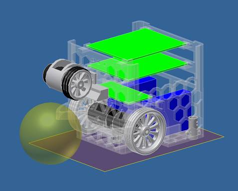
Frame 3D model: Inventor
We started to build the model from a hollow cube. From that base we started adding parts that are needed to attach the other components and extruding material to make place for sensors, LEDs, etc. The PCB's rest on small holders, as shown in the assembly. As you can see our robot is full of holes. That is mainly because before this final model, our robot was too expensive to print with the 3D printer (we needed to much material). That problem cost us precious time because of the fact that how quicker our frame was printed, how faster we could start testing our software on the actual robot.
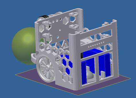
Placing the battery pack
We wanted to be able to easily remove the battery packs. Therefore we made 2 big holes at the back of the frame, as seen on the screenshot (battery packs are in blue)
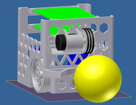
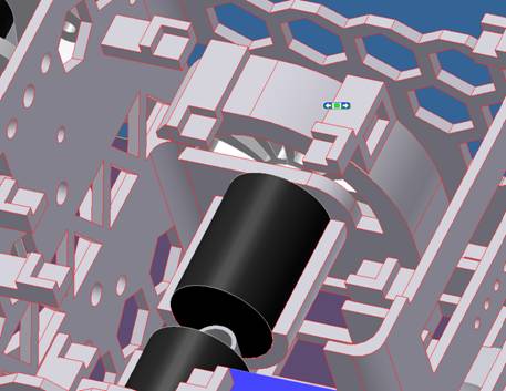
Dribbeler
When the robot finds the ball, he has to “hold it” so he can turn around his axis until he faces the goal. That is de reason we inserted a dribbler in our design. The dribbler-wheel is attached to the engine that is held in place in a printed component. This engine holder is attached with a hinge to another component that also blocks sunlight to a sensor to get better readings. The hinge is needed to allow a tolerance between the height of the bal and the dribbler.
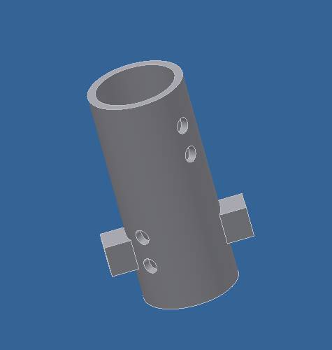
Small cylinders (for LDR sensors)
To hole the LDR's in place 3 hole's where made in the bottom of the frame. In these holes we put a small cylinder that holds the LDR and the white LED in place. These cylinders are only 3mm above the ground.
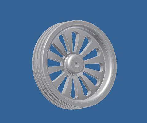
Wheels
Engines
|