In this section the hardware will be discussed, and some information about the circuits will be given.
Finding the ball - IR sensor
The ball emits Infrared light (IR). To find the ball it is a logic decision to use IR sensors. We used SFH 303-FA sensors.
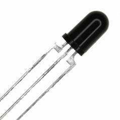
We did some tests to see how much sensors we needed to detect the ball and also to see how the sensors reacted on the ball. X is the distance from the sensor to the ball (sensor is looking straight at the ball) and the signal is measured in Volts.
X [cm] |
48 |
23 |
14 |
8 |
Max |
Signal [V] |
0.83 |
1.3-4.0 |
1.9-4.12 |
2.8-4 |
4.29 |
The measured values for a distance aren't that precise because when the ball is rotated around his axis, sometimes a IR emitting LED in the ball points directly at the sensor and sometimes not.
While testing the sensors we noticed that measured values were strongly influenced by daylight and the surrounding lights in the lab. We then decided to put extra sensors in our robot to extract the measured surrounding light from the sensors that measure the ball. The idea was that at the end we only would measure the ball and (almost) nothing else. The final robot didn't use the extra sensors, in practice these gave us even worse results. With 3 sensors in the front of the robot (one straight forward and the others respectively in a + and – 45° angle) our robot was pretty good at finding the ball. We used one extra sensor to check if the robot almost has the ball (to activate the dribbeler).
Position on the playfield- LDR sensor
To measure the greyscale we used Light Dependent Resistor as sensor.
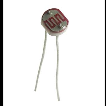
We first tested a reflective ir sensor but we saw that it was extremely sensitive to scratches in the printed grayscale and also light from the outside (even if the sensor was put in a small tube to protect it from external light sources). It is after these tests that we decided to use an LDR, with a relatively large measuring surface so that the effect from e.g. a scratch in the grayscale paper wouldn't be that much of a problem. A couple of other advantages of the LDR is that it is a cheap component and that is doesn't break easily, it's 'just' a resistor.
To use an LDR a voltage divider circuit is necessary though, so that the output isn't a signal from 0 to 5Volts but goes a bit lower then 5Volts.
Another problem with the LDR's was that the LED's that we placed above them were not always exactly at the same height etc., so our different LDR's gave different measuring values when they saw the same color.
Some hints to make a better grayscale detection system by using LDR sensors:
- Make the voltage over the LED's above the LDR's adjustable so you can fine-tune the offset error of each LDR individually .
- Maybe think of a better way to connect the LDR's and the LED's to the robot's frame (see Inventor 3D drawing)
Moving the robot:
The robot can displace itself thanks to two 12V DC motors. The front left and front right wheels are directly driven by the two engines. More information about the engines can be viewed here: info rs-components.
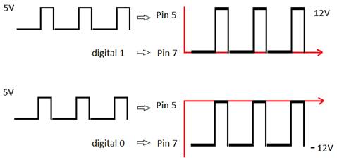
The speed of each motor is calculated by the microcontroller. A PWM signal with variable duty cycle can be created digitally with the PIC. However the output power of the PIC is too low to drive the engine. It's also impossible for the microchip to invert the current. To solve these problems, we use a full H-bridge driver (L6203).
To drive one motor, we need 3 signals from the microcontroller. On pin 11 of the L6203 we need a high level voltage (5V) to enable the IC. On pin 5 we put the PWM signal from the microcontroller. The mean voltage of the PWM signal decides how fast the motor goes. On pin 7 we can put a digital 1 or 0. A digital 0 will lower the whole PWM signal with 12V to revert the motor.
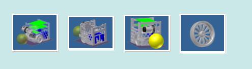
Making the PCB's:
After every electronic circuit was tested on breadboards, we decided to make real PCB's. We have used the free trial version of "TARGET 3001!" for this purpose (http://www.ibfriedrich.com/).
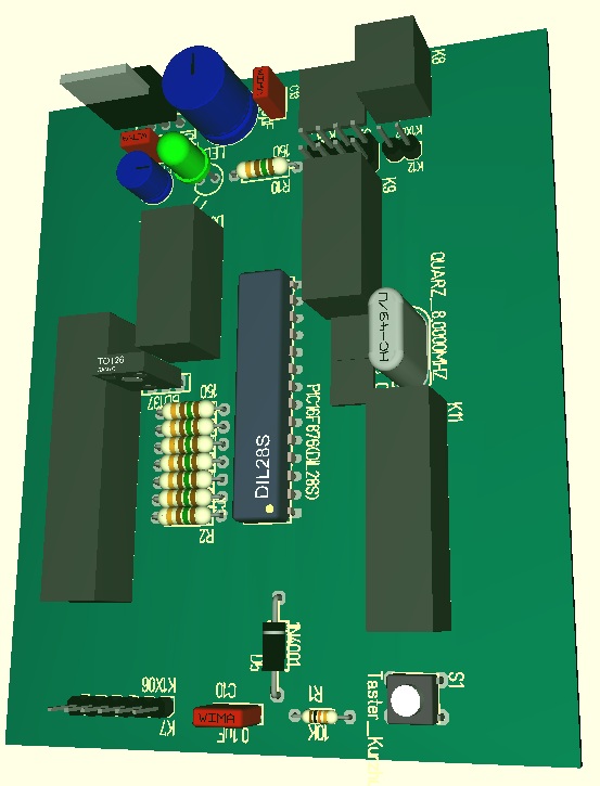
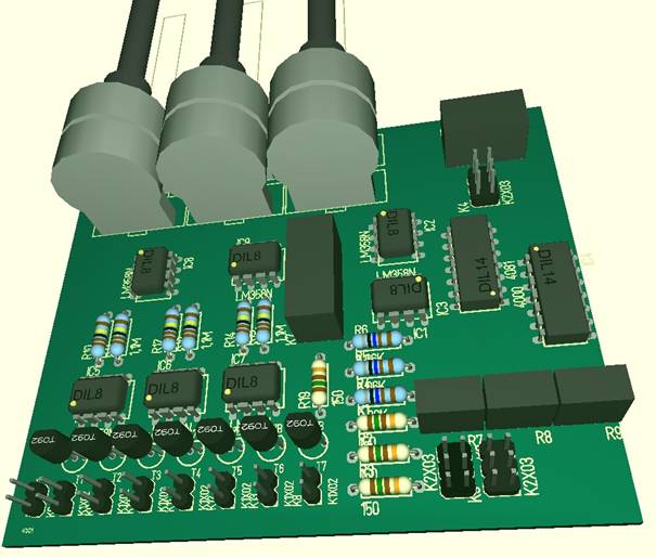
Before we could make a layout of the PCB, we need to import all the used components from the program's library and connect them just like we did on the breadboard. The next step is to place the components as we desired. Because every connection was defined in the previous step, the program can tell you which layers of copper you still have to make. After you finish this step, you can switch to a 3D view, so you can see how the finished product will look like.
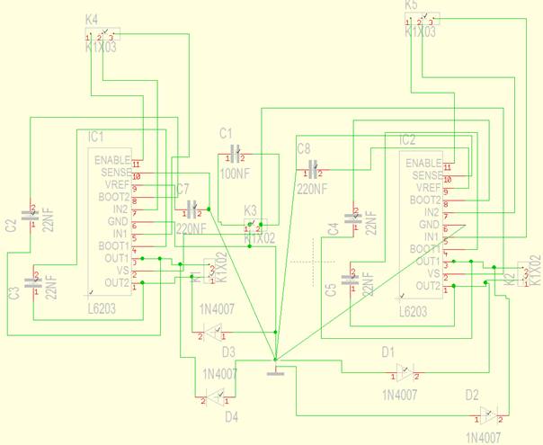
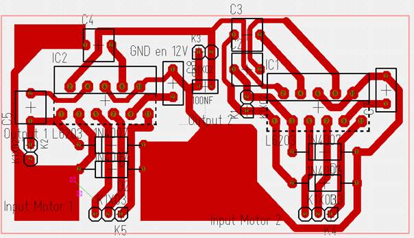
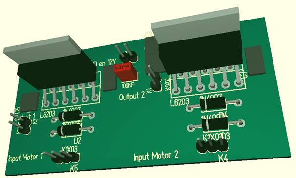
H-Bridge PCB:
Step1:
Step 2:
Step 3:
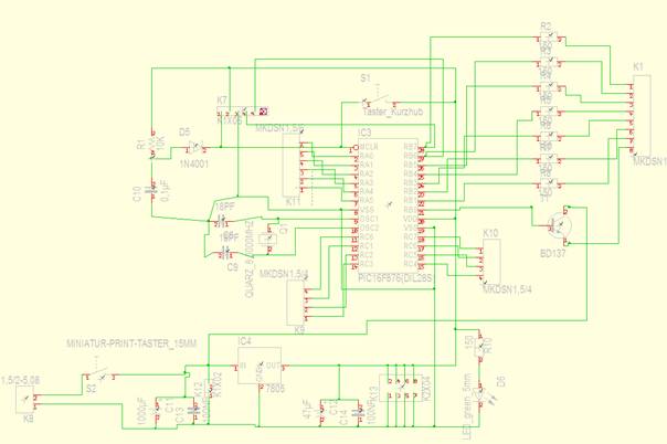
PIC microcontroller PCB:
Step 1:
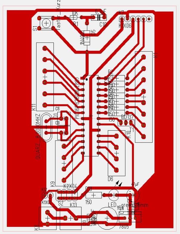
Step 2:
Step 3:
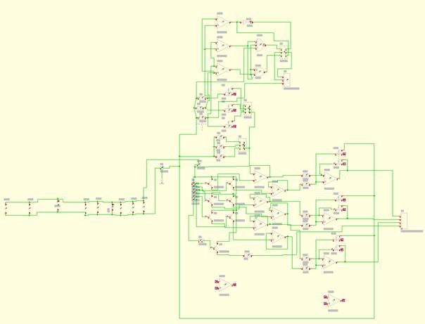
Sensor conditioning PCB:
Step 1:
Step 2:
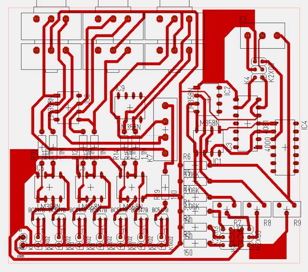
Step 3:
|