


The revalidation hand must have following functions:
- 4 moveable fingers
- 2 moveable thumbs
- Adjustable levels
- Indication if the exercise is done well
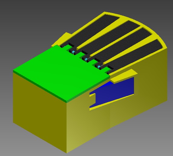
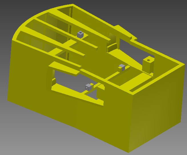
The figure above shows the mechanical design of the revalidation hand. The green part is the palm plane, the black parts are the fingers, the bleu pieces are the thumbs and the big yellow part is the casing. The reason there are 2 thumbs is because it must be able to do the exercise with both hands. The thumbs are attached at the flanks of the casing because this looks like the most natural movement.
The fingers are attached at the palm plane with a joint. The middle and ring finger stand perpendicular with the hinge bar, the index and little finger have an angle of 5 degrees with the axis perpendicular with the hinge bar. The reason for this angle is just comfort. There is also a piece of casting between the fingers because else it is possible to look into the design.
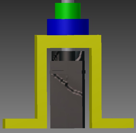
In the figures above it is illustrated how it will be possible to adjust the difficulty of the exercise. This is done by placing a spring between the finger (black) and a rail which can move vertically. The 4 springs are placed in containers on the rail and finger. The spring will ensure that a force must be exerted to get the finger down. By moving the rail, we arrange the pretension of the spring so that the force exerted on the finger can be varied. It is also important to note that we consider an exercise in which a finger rotated over a fixed angle of 15 degrees. Consider for example the case where the compression spring is relieved or in other words, the rail is in the lowest position. This is consistent with the easiest exercise because the force on the finger is the smallest. When the spring is pressed by the rail (moving upward), the compression force must increase so that the exercises become more difficult. This can also be seen by:
F = kΔx
Where the movement of the rail works on Δx.
The rails are moved by two servos, on the picture above there is only one visible. If only one servo is used then there would be a chance that the rail would bend too much that is why we opted for two servos. The position of the rail is regulated with a external potentiometer which is attached on the rail.
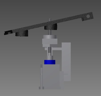
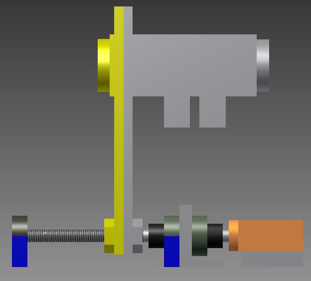
In the figure above the servo system is visible. There is a stand (yellow), a servo (black), a bearing (bleu) and a clamping screw (green).
The springs presses the rail and the rail on his turn exerts a force on the shaft which results in an undesired axial force on the servo. This problem is solved by leading of the force on the stand. The clamping screw is attached to the shaft and is pressing on the roller bearing. The bearing on his turn pushes against the stand that absorbs the axial force. The figure above does not quite match the reality, since the servo is floating, that way it is certain that the force is absorbed by the stand and not by the servo.
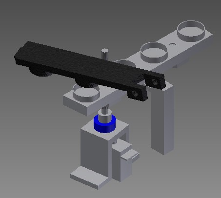
In the figure above one can see the system to adjust the level of the thumbs. The principle is the same as the finger system but there are now spring containers at both sides of the rail because there are 2 thumbs. Here also works an axial force on the servo due to the pretension of the springs. This is also solved with a clamping screw-bearing-stand system but because the axial force works in both directions there is a need to put a clamping screw and bearing at both sides of the stand.
We have noticed before that during the exercise the fingers rotate 15°, this means that there must exists a system which stops the finger rotation. This is done by putting a horizontal bar (see the figure above) where we place a pushbutton on. The pushbutton tells if the exercise is done well or not or, in other words if the finger has rotated over the full 15°. When the exercise is successful completed a green led will tell this.
Of course there must be a system to stop the fingers horizontally (because the springs are pressing it upwards). This is done by making a slot in the casing (on top near the fingertips) and little extension on the finger itself. The extension moves in the slot but the slot ends on the top of the casing so the extension cant get out of it.

The picture above shows us the realization of the revalidation hand. The left piece (where the fingers move), the fingers self and the palm plane are printed in the 3D printer. To lower the cost most of the other parts are made by hand, for example the right part of the casing is made in wood.
In the picture the guidance LEDs are also visible at the finger tips and above the thumbs.


In the picture above one finds the servo system of the thumb. The 2 springs are visible and on the wooden bar lays the potentiometer. The big white piece (which is printed with the 3D printer) is the movable rail. The servo isnt visible on this picture.