Our animatronic hand has five degrees of freedom, one per each finger; as we can see in the mechanical designs below,
each finger is composed of three pieces, in order to reproduce the human anatomy as much as possible: in fact every finger has a
proximal, an intermedial, and a dystal component. The finger's components are linked to each other and to the rest of the hand
by the use of two springs, so that lateral movements are avoided. Since we realized our device with the use of a 3D printer, we decomposed the handbreadth
in a few parts, in order to make the printing easier and not to use a large amount of plastic. Regarding the thumb, it has been designed
in such a way that, even if its rotation isn't actuated, it provides a fixed axis that lets us set it up at different angulare positions.
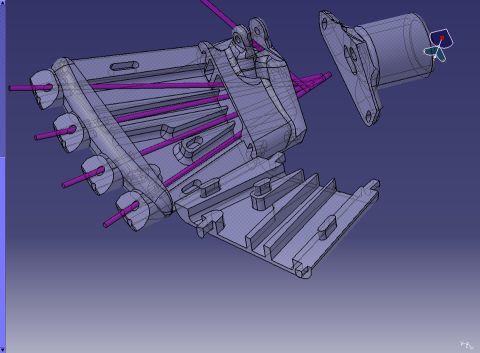
The working principle of this animatronic hand consists in having a fishing rod's wire going through each finger (each dof) and
the main part of the hand, which is then connected to the horn of a servo motor; so we have an actuation system made of five servo motors
attached on a wooden plate.
Servo Motors
The servomotors chosen from us are the HS-81, which have small dimensions and provide a very quick speed for a reasonable price.
In our research for the correct type of servomotor, the main parameter we had to look at was the speed, because our device's
main goal is the realistic reproduction of human movements. On the other hand, we thought that the torque did not represent
a very important issue in this project, even if it's not totally true as we discuss in the Troubleshooting section.
In addition, in order to increase the servomotor's rotational speed, we designed and manufactured with the 3D printer new horns,
of bigger dimension, on which the fishing wired are fixed.
We now try to explain the main steps of our assembly process:
1. Fingers: the three components of each finger, as well as the connection between the proximal part and the metacarpal upper edge of the hand, are linked by clicking the springs in the printed holes on the edges of both parts;
2. Handbreadth: all the parts which compose the base of the hand can be assembled by snap fitting mechanisms provided by specific elements present on each component; the fact that the handbreadth itself is made in two parts, makes the process of inserting the wires much easier;
3. Hand base: the two parts at the bottom of the hand, the fixed edge and the rotational joint, are just guided into each other, and their height is such that the possibility of having a part slipping out of the other one will not take place;
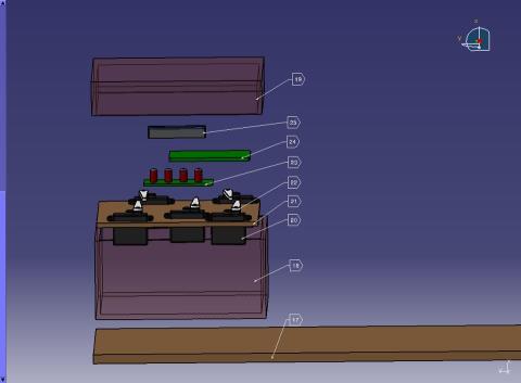
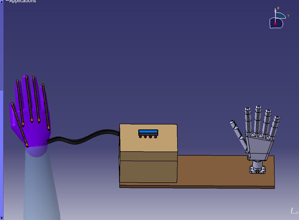
4. Servomotors: the servomotors are fixed on a wooden plate, provided with holes in it, which is screwed into a wooden box containing the motors, the PCB, and the LCD screen (these elements are treated in the Electronics section); the box is also connected to the control glove;
5. Wooden base: the base of the device consists of a wooden base on which the servomotors box and the robotic hand itself are fixed;