Electronics
Functionality
For the controlling part of our Wheeled Inverted Pendulum, we needed do design an electronic circuit with an integrated microcontroller. Our robot balances by applying a torque on the wheels. This torque is provided by two separate DC-motors (MFA/Como Drills 918D Series type 918D301/1 with RE280 motor, datasheet). To efficiently control these motors, we use 2 separate H-bridges. The output of the H-bridges, and thereby the torque, is controlled by a PWM generated by the microcontroller. To balance itself, our robot uses an IMU (inertial measurement unit). The robot can be controlled by two different GUI's: a Matlab GUI and an Android App. The communication between the robot and the GUI is performed by Bluetooth.
Schematics
In this section we describe the schematics of the 4 major parts of the electronics. All of the schematics were designed with Altium Designer.
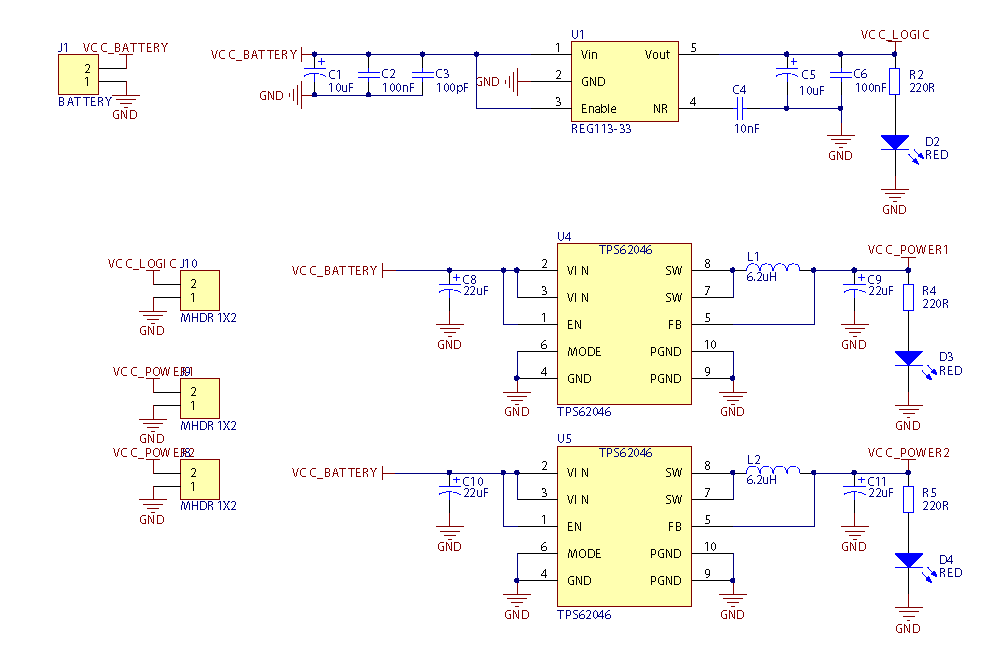
Power Supply
We supply our robot with power from a 3.7V/910mAh Li-ion battery. This power is distributed by three power converters: one for each H-bridge and one for the control/communication electronics.
To supply the H-bridges with power, the TPS62042 converter is used. This is a synchronous step-down dc-dc converter optimized for battery powered portable applications. We use the chip with a 3.3V output. The maximum current output is 1.2A.
To supply the control/communication electronics with power, the REG133-33 converter is used. This is a low-dropout regulator. We use the chip with a 3.3V output. The maximum current is 400mA, which is sufficient for the microcontroller with it's peripherals.
The datasheets for the converters can be found here:
The schematics for the power supplying part is shown in the figure below:
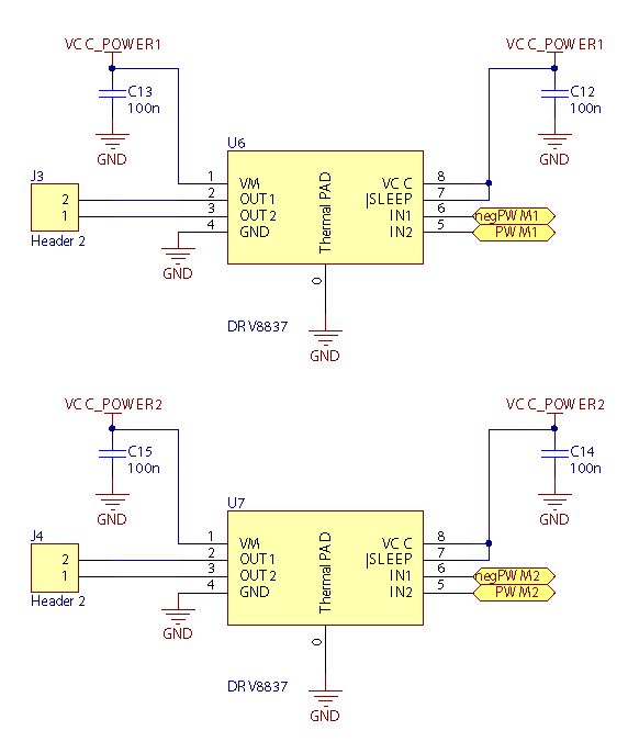
H-bridges
To control our motors, we use two separate H-bridges. With these two H-bridges, we can indipendently control the direction and speed of both motors with PWM's who are generated by the microcontroller. The H-bridges which were used are DRV8837 Low-Voltage H-bridges from Texas Instruments. We supply the H-bridges with 3,3V. The maximum current output is 1.8A. The datasheet for this chip can be found here:
The schematics of the H-bridges are shown in the figure below:
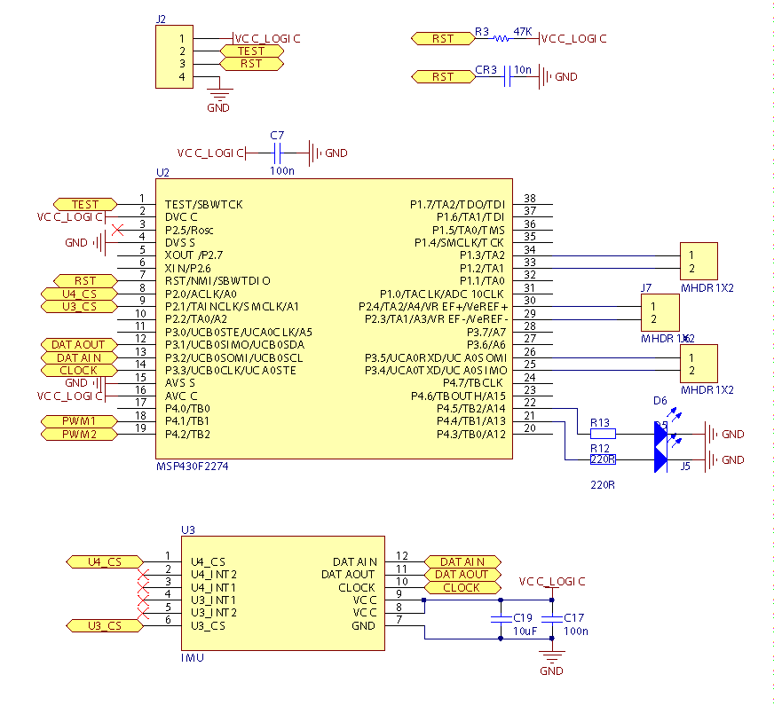
Microcontroller and IMU
The microcontroller which we use to control our robot is a 16-bit MSP430F2274 microcontroller from Texas Instruments with 32kB Flash memory, 1K RAM and 32 I/O-pins. The datasheet for the microcontroller can be found here:
The IMU consists of two sensors: a gyroscope and an accelerometer. Both sensors are mounted on a separate PCB, which can be connected to the main PCB with header pins. The gyroscope is a MEMS, low-power, three-axis angular rate sensor (L3G4200D) from STMicroelectronics. The accelerometer is a low-power 3-axis accelerometer (LIS331DLH), also from STMicroelectronics. Both chips have a digital output which is communicated to the microcontroller through SPI. The datasheets for both chips can be found here:
The schematics of the microcontroller and IMU are shown in the figure below:
Bluetooth Module
The interface between our robot and the computer gui/android app is implemented by a Bluetooth module using UART.
PCB
The PCB for our robot was also designed with Altium. The PCB is shown in the pictures below:
PCB |
Top-layer |
Bottom-layer |
Click to enlarge: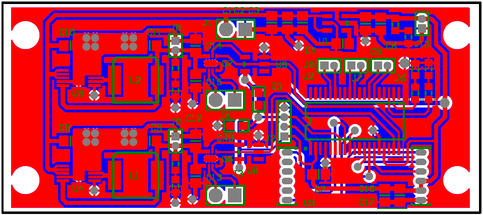 |
Click to enlarge: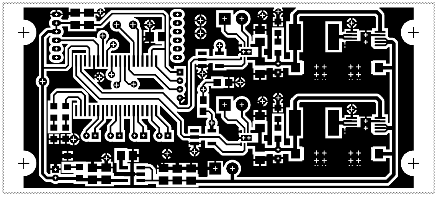 |
Click to enlarge: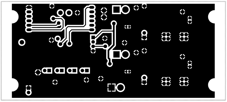 |