
| Intro | Mechanical stuff | Electronics | Software | Who we are? + useful links |
| Light Depended Resistor | ||||
| Transistor | ||||
| PCB | ||||
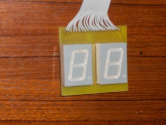
| 7-Segment Digits | ||||
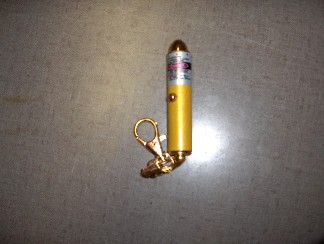
| Laser pointer |
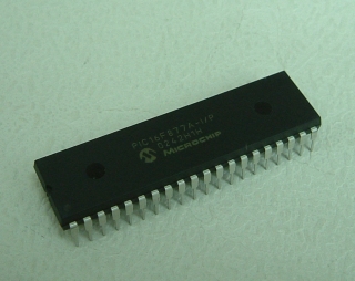
We used this available PIC, to perform our programming on. This was the most important object of our project. We won't bother you too much about this. If you do want to learn more about it, you can search on the web or visit the website of Microchip: ww1.microchip.com/downloads/en/DeviceDoc/39582b.pdf
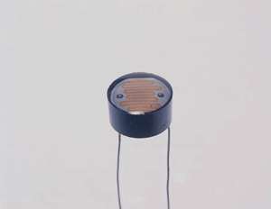
We used this type of LDR to detect when the target is shot. We used 7 of
them. One we used as a reference, we need to filter out the surrounding light,
and the others were placed on the targets.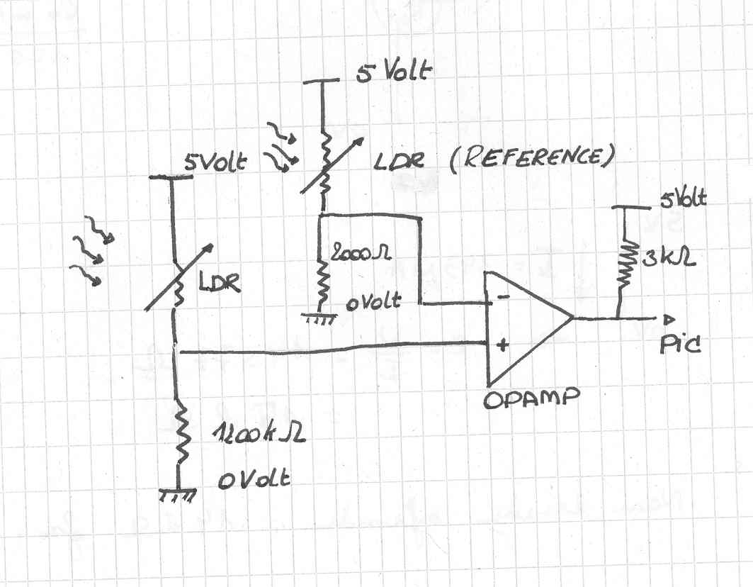 Then we designed the circuit that we would use to know when the laser beam is
shining on the target LDR. We decided to work with a comparator, to be
exact the LM339. I will not discuss further the working of the comparator, for
more information go to links. So if there is no laser beam shining on the LDR of the
target, the voltage over the ' - port' is higher than over the ' + port' . The
output of the comparator is then 0 volt. As soon as the target become visible
and the LDR is hit by the laser beam the voltage difference over the LDR drops
and the voltage over the '+ port' rises, it becomes higher then the '- port' and
the output of the comparator is 5 Volt. We send this signal to the B port of the
PIC that is programmed as an input.
Then we designed the circuit that we would use to know when the laser beam is
shining on the target LDR. We decided to work with a comparator, to be
exact the LM339. I will not discuss further the working of the comparator, for
more information go to links. So if there is no laser beam shining on the LDR of the
target, the voltage over the ' - port' is higher than over the ' + port' . The
output of the comparator is then 0 volt. As soon as the target become visible
and the LDR is hit by the laser beam the voltage difference over the LDR drops
and the voltage over the '+ port' rises, it becomes higher then the '- port' and
the output of the comparator is 5 Volt. We send this signal to the B port of the
PIC that is programmed as an input.
![]() To
control the relays we used a transistor to work as a sort of switch that can be
controlled by the PIC. We declared port D of the PIC as outputs to control the
transistor. We worked as follows to design the circuit for the relay. First we
measured the resistance and the current needed by the relay to switch on and off.
We became that he had a resistance of 500 Ohm and a current needed of 60 mA.
Then we used the gain factor, we took 175 from the data-sheets, to calculate
what the current is needed trough the base of the transistor, this was 0.343 mA. Now we
know that the voltage between the PIC and the ground is 5Volt, so we need a
resistance of 15 Kilo Ohm to place between the PIC and the Base of the
transistor. For more information about the transistor go to
links.
To
control the relays we used a transistor to work as a sort of switch that can be
controlled by the PIC. We declared port D of the PIC as outputs to control the
transistor. We worked as follows to design the circuit for the relay. First we
measured the resistance and the current needed by the relay to switch on and off.
We became that he had a resistance of 500 Ohm and a current needed of 60 mA.
Then we used the gain factor, we took 175 from the data-sheets, to calculate
what the current is needed trough the base of the transistor, this was 0.343 mA. Now we
know that the voltage between the PIC and the ground is 5Volt, so we need a
resistance of 15 Kilo Ohm to place between the PIC and the Base of the
transistor. For more information about the transistor go to
links.
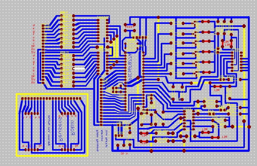
The circuit board was made using Traxmaker. Here's a screen shot of the PCB. And here you can download the .pcb-file.