|
Documentation
Hardware
1. Electrical schemes
1.1 Voltage regulator
The power source of the robot is a seriescascade of
10 1.2 V rechargable AA batteries which produce 12 V dc.
The wheel-motors and kicker-solenoid are powered by this
12 V, but the microcontroller and all other electronical
components require 5 V dc. Therefore, we need a voltage
regulator which creates 5 V dc.
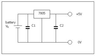
The capacitor between the battery and the regulator
is required to ensure there are no high frequency
variations in the supply to the regulator. The capacitor
after the regulator is required to supply high frequency
variations in the current drawn by the logic chips,
which the regulator is not fast enough to react to.
top
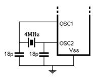
1.2 Microcontroller
The microcontroller is the heart of the robot because
it registers all the sensor information, processes this
information and finally controls the actuators
accordingly. We chose to work with the PIC 16F877A,
because it has a large number of input/output pins. The main advantage of this chip is that it contains
already all the necessary modules for information
processing (CPU, program and data memory, input/output
interface,...). Therby, we don't need many other
electrical components to make it work. Only some basic
requirements are necessary which will be explained
below.
Clocksignal
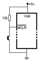
Reset
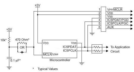
ICSP
To load the program into the microcontroller a
special connector is used (PicKit2) which uses In-Circuit Serial Programming
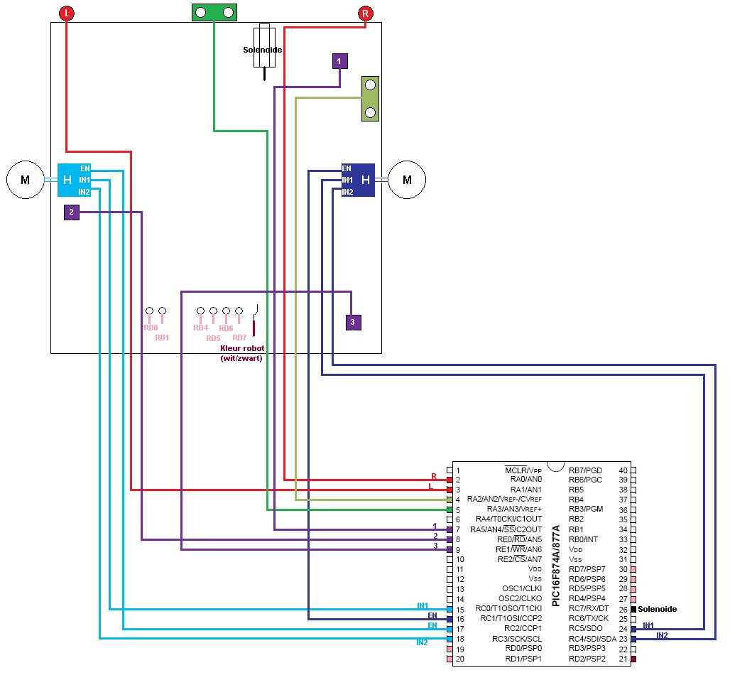
On the figure below, you can see the signal routing
between the microcontroller and the sensors, actuators,
switches and leds.
top
1.3 Sensors
| Function |
Name |
Amount |
color in the
signal scheme |
| Greyscale and Y
position detection |
HOA1405 |
3 |
|
| Ball-posession detection |
GP2D12 |
1 |
|
| X position detection |
GP2Y0A02 |
1 |
|
| Ball detection |
SFH 303 |
2 |
|
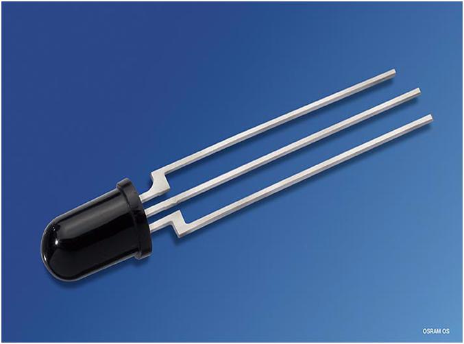
IR-ball detection
An infrared sensor was used to detect the ball. The
SFH 303 has a spectral range of sensitivity of:
750nm-1100nm. The maximum sensitivity is around 990nm
which is close to λball = 940 nm.
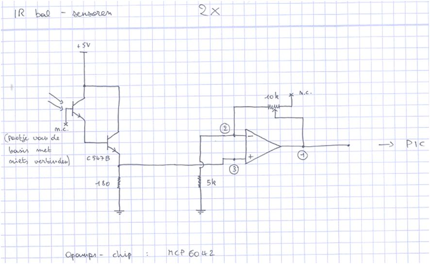
Originally, the sensor was placed in a darlington
arrangement to amplify the current coming from the
sensor and then the voltage was amplified (see next
figure) but afterwards this seemed not needed since the
output voltage was large enough and we also had some
problems with our opamps. Thus we connected the sensor
directly to the microcontroller.
top
Side detection
The walls were detected with an infrared detector:
Sharp GP2Y0A02. The electronic scheme can be seen in
next picture. The potentiometer was used for calibration.
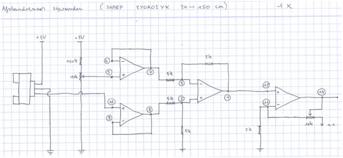
Distance to the ball
To detect the distance between the ball and our robot
we used a sharp GP2D12. The electronic scheme was the
same as in previous figure. It might not be logical to
use such kind of sensor but during our test we were
satisfied with the generated output voltage of the
sensor because there was not a lot of fluctuation this
value. The idea was to put the sensor 4 cm behind the
place where we would collect the ball such that it would
give a maximum output.
top
Grayscale
Three IR-reflective sensors (HOA1405) were used to
measure the grayscale and orientation of the robot.

Next figure shows the electronic scheme for this sensor:
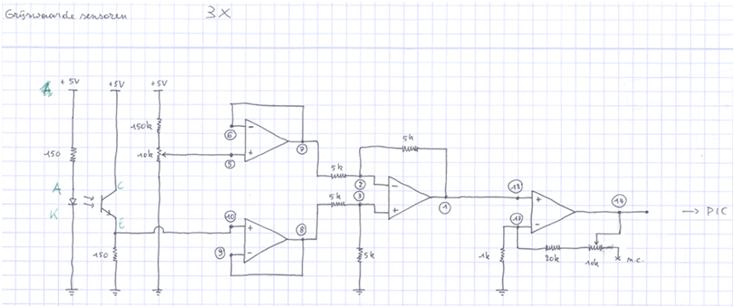
The potentiometer was used for calibration, i.e. to
remove the offset when the sensor was placed above the
black color. This is done by using a difference
amplifier with no amplification and afterwards the
amplification can be determined manually such that a
full range (0 - 5 V) was achieved. Note that the optimum
point of response of this sensor is 5 mm, so we also
took that into account for our design.
top
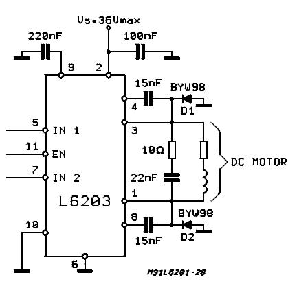
1.4 ActuatorsDC motors
The robot has 3 wheels of which 2 are each driven by
a dc motor. The rotation speed and -direction of these
motors are controlled by a H-bridge chip. We use 3
signals per H-bridge from our microcontroller to control
the H-bridge: a PWM signal on the Enable pin and a high
or low signal (5V or 0V) on In1 and In2. The signal on
In1 has to be the complement of the signal on In2.
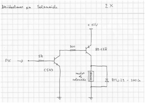
Solenoid
We used a pull-type solenoid for the ball kicker,
which operates on a nominal voltage of 12 V dc. It is
activated by a short signal from the microcontroller,
which gets amplified by 2 transistor in Darlington
configuration.
top
|