We experienced several problems implementing the Hall sensors and their accompanying PCB.
 Our first batch of sensors were the small rectangular onces, since we were aiming for a compact design. However, testing these sensors wasn't easy because of exactly their size. We found it difficult to solder little wires to the connections to enable testing with the Arduino. The wires were prone to snapping and difficult to keep connected to breadboard or Arduino connectors. Finally, we managed to determine they were fit for use on our printed circuit board.
After soldering the combination of sensors, resistors and LEDs to the PCB, the latter didn't work as expected. There seemed to be some shortcircuiting going on on the board, because multiple control LEDs blinked at the same time.
We were forced to order a new batch of Hall sensors, but this time we encountered an apparent structural problem. We didn't get stable and reliable output from the sensors, and they didn't seem to respond to a magnetic field as expected. Even though they had a different design, they were the same type (polarity)and should have had the same characteristics as the previous ones. This problem was confirmed by two team members who examined the sensors independently, but to no avail.
Because of upcoming deadlines and timing, it was impossible to investigate this problem further. Thus, we decided to rebuild the original PCB to a monitoring device using the LEDs in combination with a demultiplexer. The Hall sensors's function was replaced by a another potentiometer, well aware that this choices reduces the life span of the design.
The Hitec HS-81 wasn't able to deliver the needed torque at a sufficiently high speed in combination with our transmission.
The solution to this problem led across all kinds of motors, until we had to settle for a combination of a higher power servo in combination with a more direct transmission.
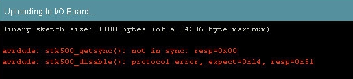 We used multiple Arduinos for parallel testing and not having to rebuild rather complicated breadboard setups. One time, our Duemilanove stopped working, along a "not in sync" error message. The power supply of the board kept working, however we weren't able to upload sketches anymore. Causes could be sought among overpowering of digital in and/or output pins, shortcircuiting etc. Fact is that Arduino boards have to be handled with great care. Shortcircuiting can happen easily when using breadboards and currents starting at 40 milliamps can already damage the respective pins.
The PCB design took place at an early stage in the project, and therefore also the allocation of Arduino pins and the mapping to the PCB. Because of a shortage of pins, we opted for the use of the serial communication pins 0 and 1. These pins are used by the Arduino while reading and writing serial data from and to a computer via USB. However, since our design would function on an external power source, they could theoretically be put to good use. In reality, however, this didn't turn out that well. When using pin 0 as one of the LCD pins and in combination with an external power source, the LCD didn't produce the desired characters. Comparison with a breadboard setup confirmed that this was indeed the problem.
A rather drastic solution here could be to mod the PCB and LED connections and try to switch some.
These often weren't great. We received our springs (ordered around two weeks after the start of the project) only friday afternoon, the week before last. Hence, we weren't able to begin testing the whole design until then.
Because our springs were late, our mounting plan of the springs onto our system failed, and we weren't able to mount them properly. Thus we failed to have a good connection of our pulling strings to the springs and this limits the pull length so we can't use the whole 5 cm.
Our ordered worm gear wasn't delivered before the presentation of 28 June 2011 (3 weeks overdue and counting), so we needed to figure this problem out using another setup, which is of course less profitable.
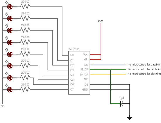
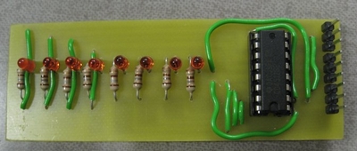
Because there was no more use for the multiplexer, but the relevant PCB was still intact, we decided to tweak it to work the other way around. The result was a demultiplexer, which we can use in combination with the LEDs on the PCB to visualize the progress along a stroke. Again, we encountered the problem that during the assembly, a LED had broken down.