Component selection
In this section we will go through the list of components needed to construct our robot. All the data sheets can be found here.
1. The control system
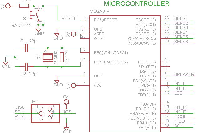
The initial idea was to use an Arduino Uno microcontroller board that we would program, and then “clip” a PCB board directly on it, to connect the different pins. However at our half-time presentation, it was suggested that we place the microcontroller directly onto our PCB. The microcontroller in question is:
* Microcontroller ATmega 328
2. Movement
To move our robot, motorized wheels would be used. We decided to use the motors used by a group from a previous year. This is because the motor characteristics corresponded to our needs and allowed us to cut costs by reusing them. To control the motors, two digital signals are sent from the PMW outputs to two H-bridges to drive the 2 motors.
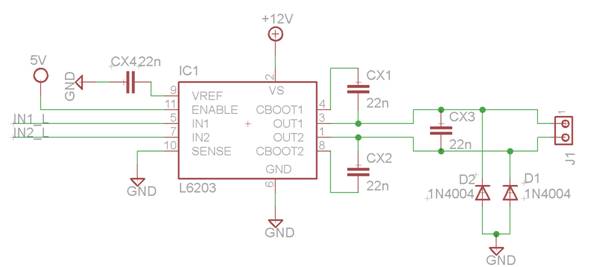
The used H-Bridge is as shown: an L6203. The schematics were made based on the data sheet. The motors that were recuperated are from the 1271 series.
3. The detection of the obstacles
For the detection of obstacles we had to choose between ultrasound sensors and infrared sensors. Although the precision of ultrasound is higher, in the aim of reducing costs, we opted for infrared sensors. Again, these sensors were available from previous year robots. We used the Sharp IR Range Finder because they can work accurately outside.
Only 6 analog pins were available, so this is how we placed our 6 IR sensors:
- 4 sensors are dedicated to the detection of the obstacles in the front.
- 1 sensor is dedicated to the detection of holes in front of the robot.
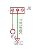
- 1 sensor is dedicated to determine if someone is holding the robot (placed at the rear of the robot).
Of course different sensors were used for the bottom and the front of the robot. The front sensors need to detect a range of around 20cm where as the sensors underneath have to detect a distance of around 5 cm.
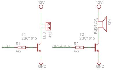
4. Attracting attention
Once the robot is obstructed, it needs a way of attracting the attention of passers-by. As stated in our concept description, we will use LEDs and a buzzer. We use 6 LEDs per cheek and the buzzer used is a KSS1201.
The wheels will also be activated to move a bit on the spot to attract attention. There are 2 different modes of activation. Either the robot sees an obstacle, the LED’s flash and the buzzer plays a sound with a low frequency ("beep beep") and when picked up the LEDs stay on and the buzzer plays a sound with a higher frequency ("Pika Pika").
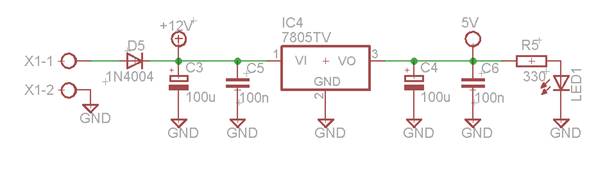
5. Power supply
The power supply of our robot will be batteries placed inside the robot (10*1.2V). Two small wires will stick out of the robot to allow recharging of the batteries between uses. A voltage regulator circuit is used to create 5V for microcontroller and other components.