
 Electronic
Arduino
For reason of simplicity we decided to use an arduino instead of a PIC (lot of libraries could be found easily on the web).
 PCB
PCB
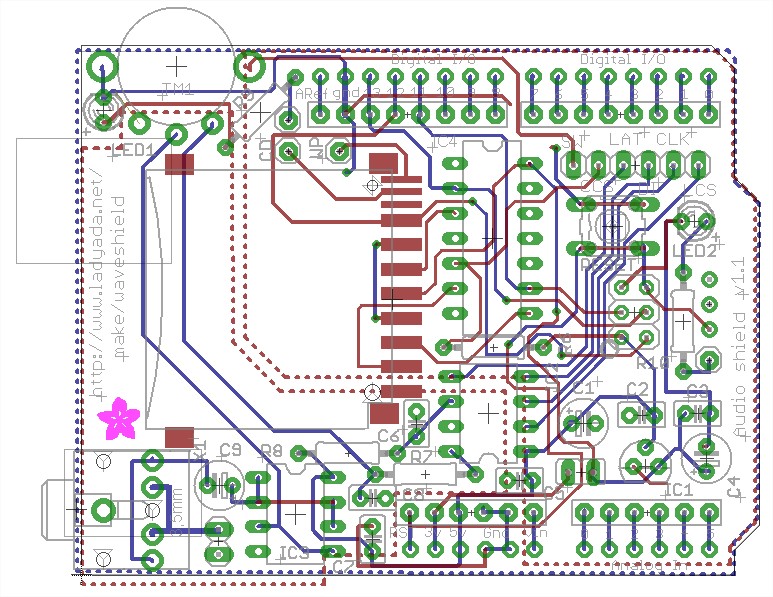
On figures 1-2 we have our PCB and on figures 2-3 the audio shield. Our PCB is used for the sharp sensors, binary counter, switches, push button, motor and the audio shield is only used to produce sound (the role of each component will be explained later).
So we can notice that we have 2 PCB’s. Normally our PCB is mounted on the arduino and the audioshield is mounted on our PCB (we have 2 floors). In practice we didn't use the audio shield (it will be explained later).
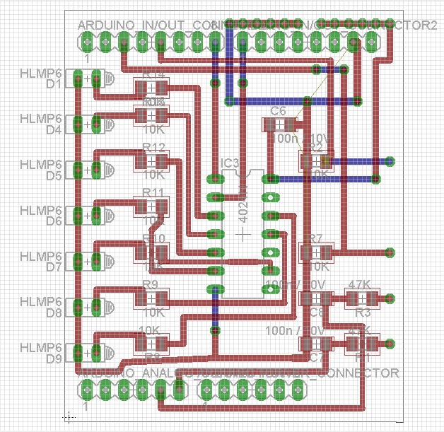
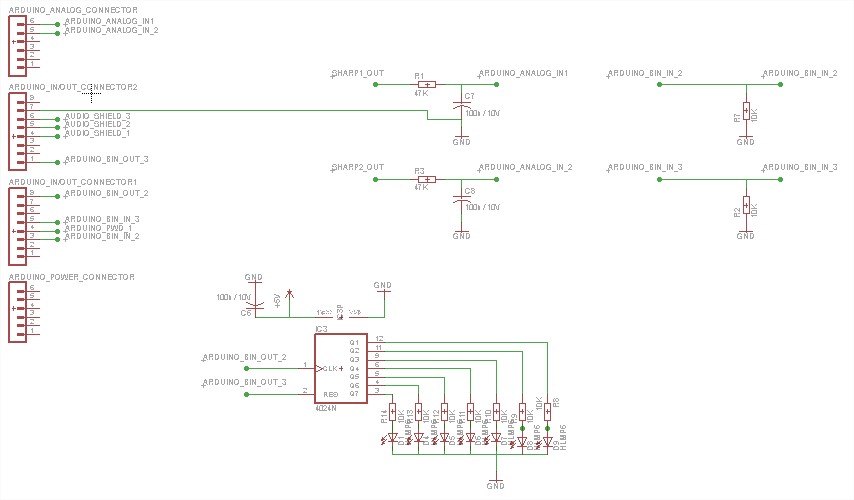
Our PCB
Motor
We decided to use a servomotor already available in the lab. By making some testing (we linked the axis of the motor to different masses with a string and checked that the motor could pull the mass). We noticed that the motor could provide a sufficent torque to move the robot. Since it's a servomotor there are 3 wires: one for the ground, a second one for the alimentation and a last one to operate the motor through the arduino. We also put a transistor bewteen the arduino and the motor to provide enough current to the motor.
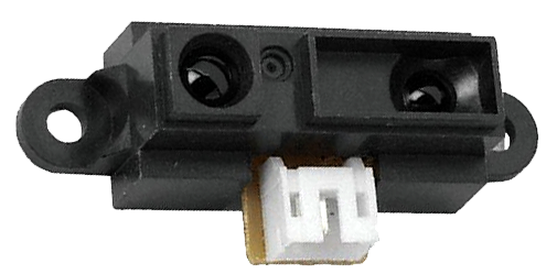
Sharp Sensor(GP2Y0A41SK0F)
We used two sharp sensors to check if there were obstacles in front of the robot. Basically the sharp sensor is an analogic sensor that gives a certain tension depending on the distance at which an obstacle is detected (the range of our sharp sensor is 10-80cm). As we just wanted to know if there is an obstacle at a given and constant distance we could simply use an operational amplificator as a comparator to check this condition. It was more simple to connect the sharp sensor to an analogic input and only check directly the tension of the pin. We wanted to put a low filter between the output of the sharp and the input of the arduino but the tension was too small and as we realized it worked by directly connecting it to the arduino, we decided in the end not to use the filter (in practice we simply decided to directly connect the sharp to the arduino).
Push Button
We have a push button that detects if someone is lifting the robot.
Switch
There are 2 switches. The first one is connected to the batteries and is used to switch on/switch off the robot (so there is no connection with our PCB). The second one is used to switch the modes (human/robot) of the robot. As the audio-shield did not work, we did not use the push-button to change the mode of the robot: indeed the 2 modes were supposed to interact through their peculiar voice (human voice/robot voice for example).
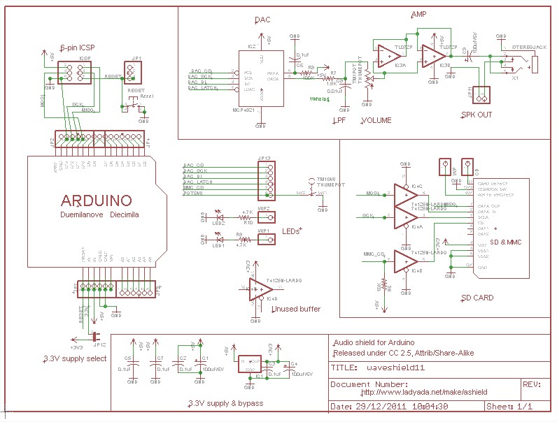
Audio Shield
We wanted the robot to interact with the user through sound and as we found a ready made PCB to do so we decided to use it. The main components of the audio shield are:
- The SD card on which all the sounds are registered.
- The SD card holder that holds the SD card and connect it to the PCB circuit.
- The Level shifter for SD card which allows the communication between the arduino and the SD card.
- The DAC which converts the binary signal of the arduino to a digital one of 12-bits.
- The voltage regulator that lower the tension from 5V to 3.3V in order to feed some components of the shield.
- The operational-amplifier which works as a buffer to feed the headphone.
Everything (board, schematic, required components, ...) can be found on this website.
We could also buy it but the normal delivery time can go up to 5-6 weeks or 5 days but at a much higer cost (3 times).
All the components required to mount the audio shield were not available so we changed some of them: we used an other SD card holder (FPS009-2405-0:CARD) and an other headphone jack. We also decided to use the resistances and capacitors already available in the lab instead of the ones suggested.
Sadly, the audio shield did not work. The reasons can be multiple: a soldering not correctly made, a component could be broken because not all the solderings were correctly made before we first tested the audio shield, a problem in the code, ...
Also some holes of the audio shield were supposed to be metal-coated (connection between the top and the bottom of the PCB). But we did not notice at first sight that we had to do the coating by ourselves since it's not done by the printer used in the lab to make the audio-shield. This led to some problems.
So to solve this problem we just decided to directly connect a speaker to the arduino (we also put a transistor between the speaker and the arduino to provide a higher current and so increase the volume)
The principle can be found on the website of the arduino.