
 Mechanic
 Functional analysis
These are the requirements of our Project:
- The robot must move straight forward
- The robot must have two interchangeable covers
- Obstacles and holes must be detected and the robot has to stop
- The robot must be able to call for help
- The robot must be stable in order to move in an urban environment
- The speed of the robot should be approximately the speed of walking human
- The robot should detect if he is being lifted from the ground
- In order to reach his destination,it must be indicated somehow
- Modifications should be easily performed, the access to the PCB must be taken into account
- The amount of plastic should be optimized
- The robot must be independent: he will be supplied by a battery
Conceptual design
In order to meet our requirements the following concepts have been imagined
- Motorization:
- To simplify the regulation of the direction, we decide to use only one motor.
- For the stability of the robot we use three wheels forming a large triangle base.
- As we chose to use three wheels, the motor can be fixed on the isolated wheel or on the axe between the two other wheels. We chose to fix the motor on the isolated wheel directly to avoid complicated transmission design.
- To choose a motor that fits our requirements we computed the torque and the rotational speed that we expect will be necessary for the movement. This leads us to the following motor Como Drills 980D161. Our final motor is not this one: we got one from the lab. We made tests to know if the torque will be sufficient. This motor should be sufficient but the speed will not reach the desired one. As the speed of the robot is not of major importance, this motor is the one we use.
- Cubic Structure:
- The structure has to be economic in plastic thus we cannot build a box in a single print with all the emplacements for our sensors and actuators. We decided to build corners in plastic to assemble plates to form our box. Each part needs thus a fastener that will also be fixed on the plate.
- To permit an easy access to the PCB, the back plate is easily removable by using a sliding panel. The design of the backside corners must thus be specific.
- The parts that will be fixed on the plates include : PCB/Battery fixation, motor fixation, back wheels axe fixation, flag fixation.
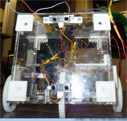
- Two Shapes:
- The first shape ("robot" shape) is created be using plexy glass panels. In that way, all the inside parts are apparent and the box look like a robot and is not “human friendly”.
- The second shape is made out of wood, it is also a box, painted and decorated to make it seems “human”.
- The second shape will be easily added or removed on the plexy structure thanks to fixations that are gliding inside each other.
- Please Help me!
- The robot is supposed to ask for help to reach his destination. We chose to make him able to talk. Therefore, we use a speaker and we must take it into account while we design the plates.
- To permit the different behaviors, we will use a switch that switches him from human to robot behavior and vice versa.
- In order to thank the people who help him, we implemented a sensor which detects when the robot is being lifted.
Embodiment Design
Based on the conceptual design, a more accurate approach to the final design can be initiated. The embodiment design consists in the explanation of the detailed design. All the different parts of the robot will be studied apart from each other. The functioning of the assembly is already explained in the previous section. We will begin with explanation of the core structure of the robot, which will lead us to the motorization device and to the fastening elements, and we will end with the external cover of the humanoïd version of the robot.
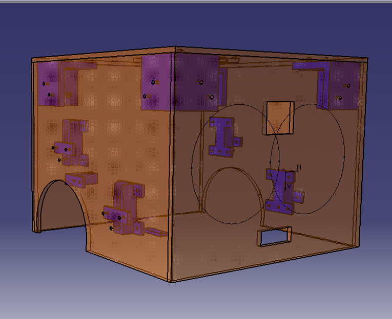
The Core Structure
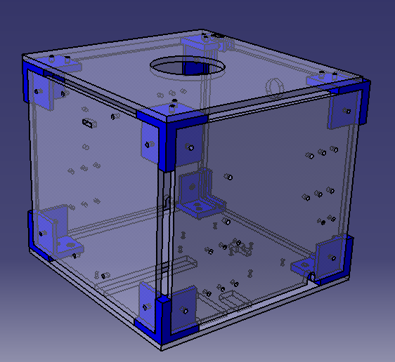
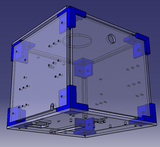
The core structure is the assembly of rigid elements that will serve as foundation to the robot. The two pictures above show this core structure. Some information may already be deduced from these figures:
- As it was said in the conceptual design, this structure is composed of rigid panels of plexiglass (4mm), assembled by means of printed corners in plastic (represented in blue).
- There exist five different types of corners depending on their position and their function. The four corners at the front of the robot are identical. The four others, at the back, are complicated because of the presence of a sliding panel.
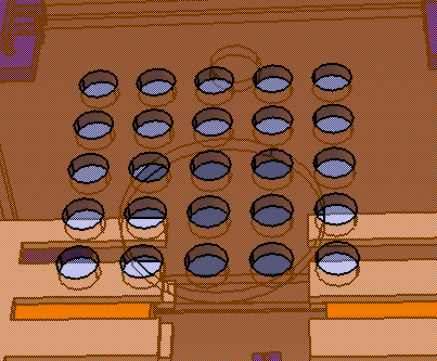
- All the panels are cut by laser cutting. Each hole allows the fixation of an element (bindings,…), the motion of the first wheel or an access from outside (cables, switch to change of behaviour, switch to shut it down, flag,…).
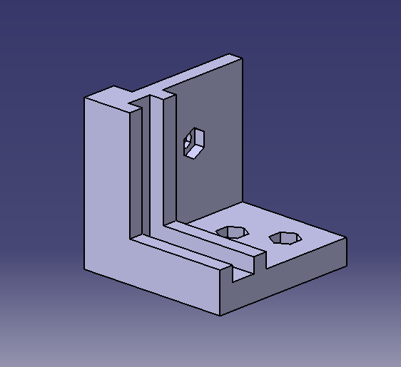
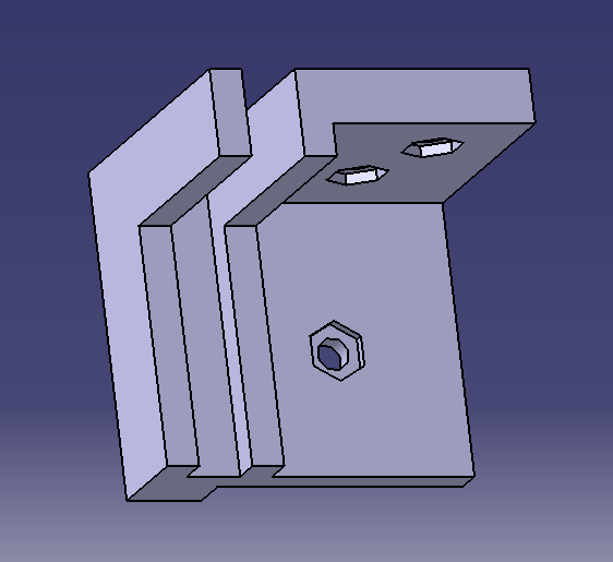
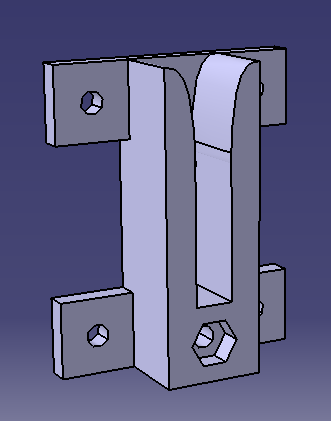
Front Corners
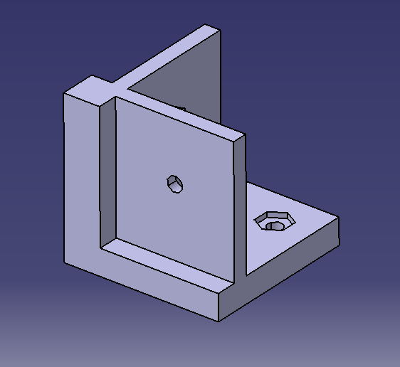
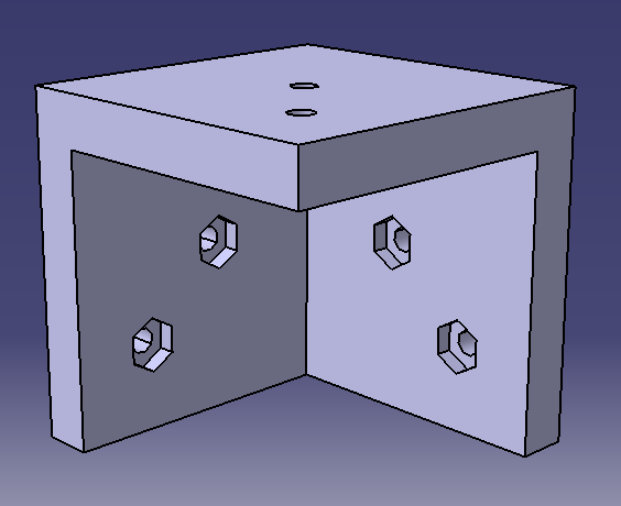
First, the front corner will be outlined. The piece is designed as follows:
- Two faces are hollowed out to allow a quasi-fixation of both sides panels. These panels are then bonded by bolts and nuts. It is important to notice that the third side of the corner is not hollowed out. This is due to the restrictions of the 3D printer. Indeed, this printer is based on a layered manufacturing technology that doesn't use any support material. Because of that, the printer would be unable to reconstruct the piece if there wasn’t a filled bottom side. The printing of this piece requires reconstruction by starting with the filled side. The holes dug in the others sides are sufficiently small to allow the deposit of material above them and thus the printing the entire piece is possible.
- Two holes are drilled into the bottom faces to prevent any rotation of the bottom (or top) panel.
- In addition to holes, hexagonal shapes are dug into the pieces to allow the fixation of the nuts.
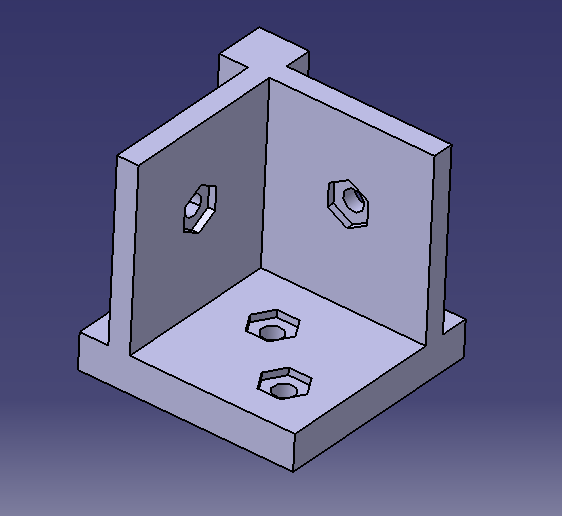
Back Corners
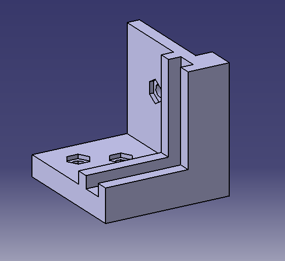
The four front corners were designed along the same lines as the back corners.
Actually, the only functional change concerns the sliding panel.
To lead the panel through corners, a guide is built out of two small edges, replacing a side of the front corner.
The last back corner (top right) allows putting a screw parallel to the panel placed in a horizontal position.
The access to the internal components of the robot is eased by the absence of a third side of the corner, along with the sliding panel.
The Motorization Device
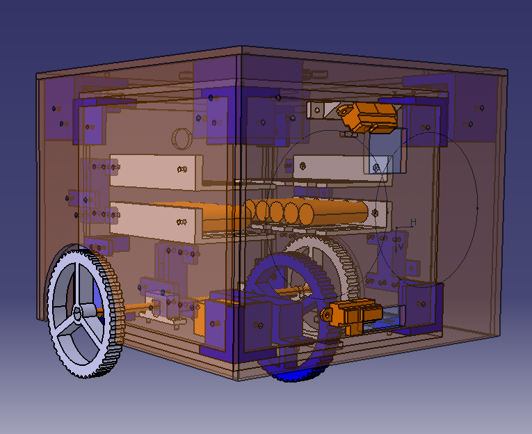
The motorization device is, as it was explained in the conceptual design, based on a system comprising three wheels, of which one is driving. The next picture depicts this design.
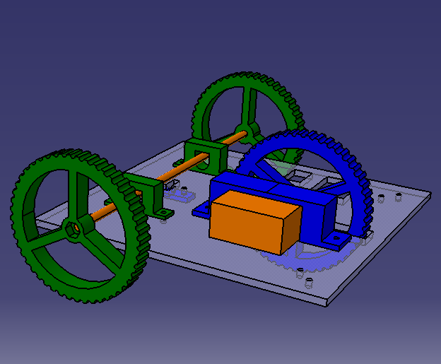
The following elements are shown on this picture:
- The driving wheel, in blue.
- The motor, in orange (represented by a block).
- A binding to fix the motor, in blue.
- The non-driving wheels, in green.
- An axis between these two wheels, in orange, made of a threaded rod.
- Two bindings to lead the axis of the wheels, in green.
- A limit switch below the center of the axis (non represented) and its binding, in blue (below the panel).
- A binding to fix the motor, in blue.
The main elements will be described below.
The Motor
To prevent excessive purchases, the motor was chosen between the available stocks in the laboratory. The selected motor is a modified servomotor, whose torque is sufficient. The limitations concerning the rotation were mechanically removed. These modifications allow the infinite rotation of the axis. Unfortunately, the rotation speed is not very performing and one can expect that the robot will be slow. In regards to this limitation, wheels with alarge diameter were chosen.
The Wheels
Two types of wheels were designed: the driving wheel and the free wheels.
These two designs are distinguishable by the size of the central part of the wheel,
by the shape and by the size of the drilled holes.
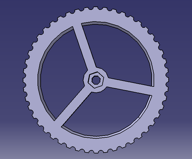
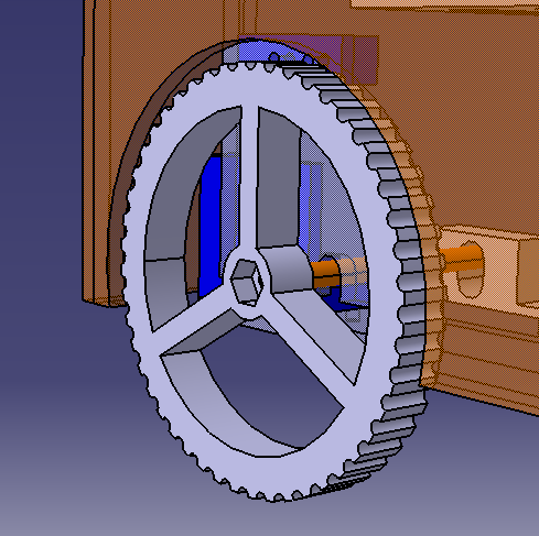
This wheel was designed as follows:
- To prevent waste of matter, and consequently increase of costs, the wheel is hollowed out. Three radii are conserved to guarantee a minimum robustness.
- The external surface of the wheel is jagged to provide a sufficient adherence with the ground. Indeed, the ground on which the robot will circulate, could be rocky and stony. With a smooth wheel, there could be no adherence.
- A central hole is configurated to fix a nut.
The Axis Bindings
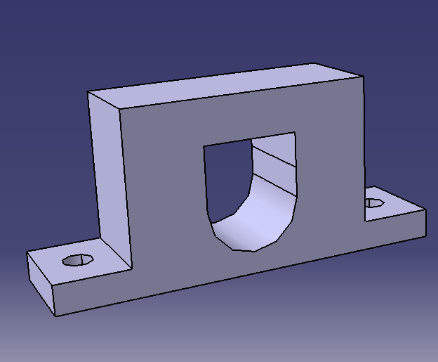
In order to detect if the robot is being lifted, the axis can take two positions: up and down. Thus, the axis must be guided when in intermediate positions. It is exactly the role of this element. With the help of two washers and several nuts, it is possible to keep the axis horizontal and aligned with the center of the robot.
The Additional Elements
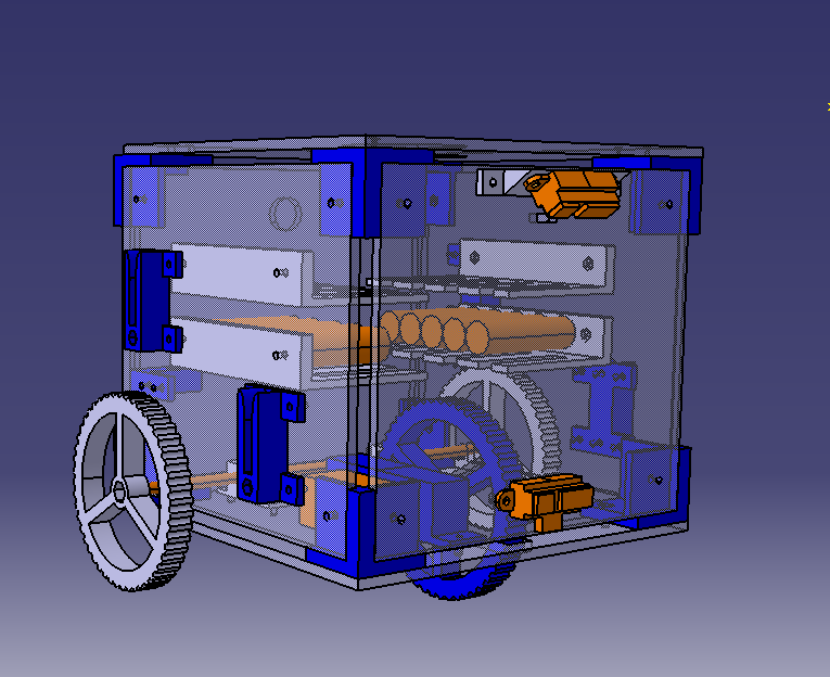
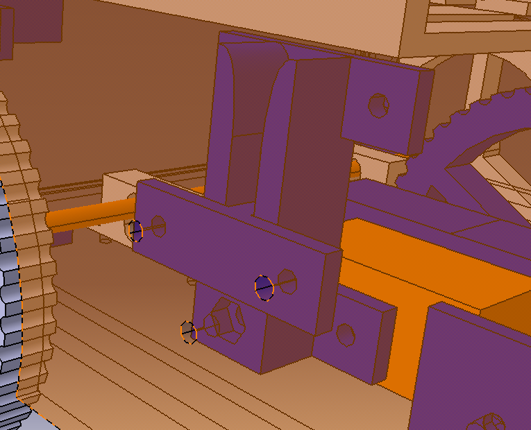
The robot filled with all the components is represented just below:
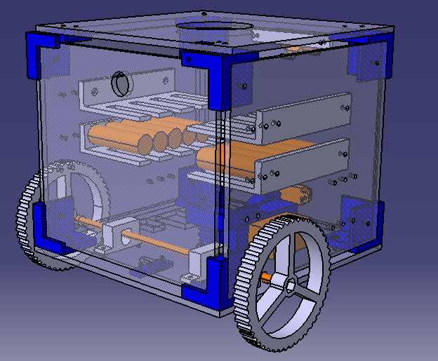
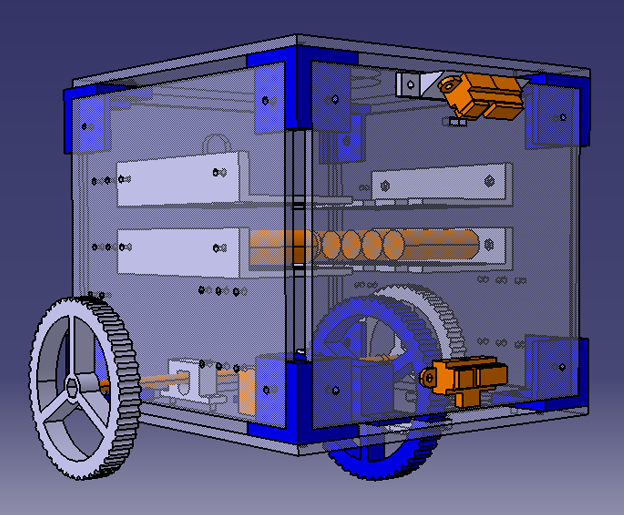
Several new elements appear in this picture:
- The Sharp sensors.
- The bindings of these sensors.
- The power supplies, which won’t be described in this section.
- The bindings of the PCB and the power supplies.
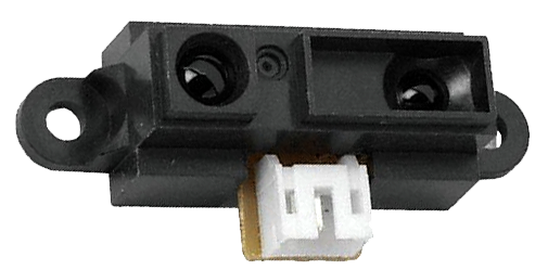
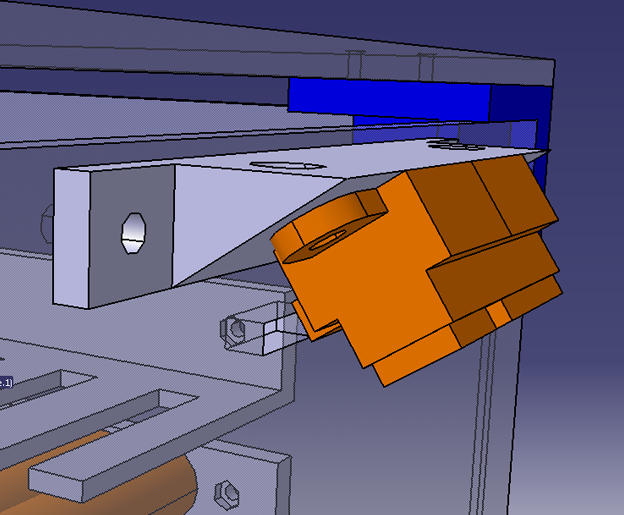
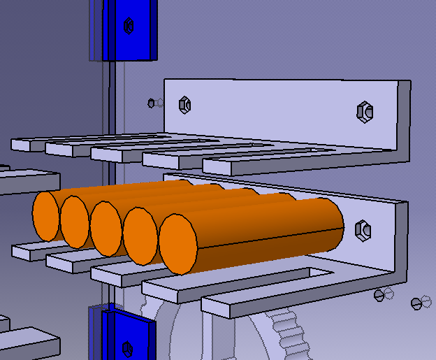
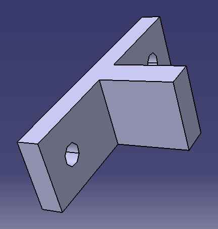
The Sharp Sensors and the Bindings
As it was already mentioned, distance sensors are required to detect cliffs and obstacles. Because of the low speed of the robot, distance sensors with small detection distance can be used. Sharp sensors (in orange in the second picture) with a detection distance ranging from 10cm to 80cm were chosen. The upper Sharp sensor, which allows the detection of cliffs, must be tilted at a certain angle. The chosen angle is about 56°, when placed 20cm above the ground. To fix the upper Sharp sensor, a binding was designed which allows an angle between the panel and the sensor.
The PCB and Supplies Fasteners
To fix the PCB, the audioshield and the power supplies to the side panels, a same piece was designed. This element acts as a tray. In this tray, spaces were hollowed out to provide easy access between each level of the robot and consequently, to allow the passage of cables.
The Cover
In addition to this core structure, another cover was designed to slide on the structure and fixed on it. The following picture shows the main structure (where small guides were added), the cover and the global assembly. Several new elements appear:
- The cover panels.
- The corners to link the panels.
- A male-female device to tie the cover with the structure.
The Panels
In opposition to the structural panels, the cover panels are made of 3mm thick wood. Indeed, this cover requires some opacity to conceal all the internal components. Some holes are hollowed out to prevent problems with the distance sensors (as shown in the first pictures), with the wheels (second picture) and with the speaker (third picture).
The Corners
The cover corners are designed the same way as the structural corners with the following slight difference. In order to prevent any gap between the panel edges, the sides of the corners aren’t hollowed out. Thus, two bolts are required to prevent any rotation of the panels.
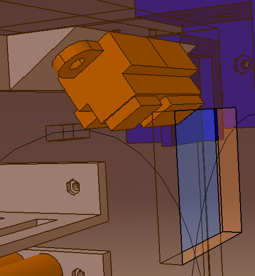
The Fasteners
The link between the cover and the robot is achieved by spigot end parts, fixed to the cover, and socket end parts, fixed to the robot. The following picture shows its functioning:
The socket end part is designed as follows:
- There is an entry at the top of the piece to allow the passage of the spigot end part. This entry is slightly rounded off to easy the manipulation.
- A hole is dug into the bottom of the piece to fix a bolt through the cover which is thus blocked on the robot.
The Final Assembly
Download the Pieces