TEAM1 - Project - Brachiationbot - 2012-2013
ASSEMBLY and TEST
On this section, you will find :
Firstly, some pictures of the brachiation robot realization.
Secondly, some video tests of the brachiation robot.
Finally, we will talk about the further improvements.
1. Brachiation robot
1.1 Mechanical structure
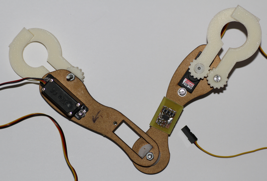
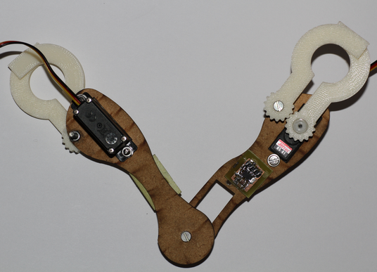
The total weight of the brachiation robot is 77g with a height of 120mm.
As the main servomotor was taken off, its total weight was 62g.
On the figures below, only the final robot is shown where the main servomotor (responsible for rotating two arms)
does not appear due to some reasons which will be explained in the "video" subsection.
1.2 PCB
1.2.1 Complementary PCB
The "complementary PCB" for the gyroscopes were sticked with super glue on each arm as shown at the Figure 1 and 2 above.
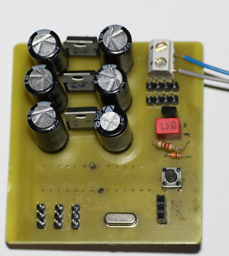
1.2.2 Main PCB

2. Video tests
Video 1 below shows that there was effectivily swinging effects and back-reactions of the robot by using one motor.
First step
We decided to verify if the implemented open/close function of a gripper worked; it was a success but the servomotor was damaged due to mishandling during which the motor did not stop when the gripper was already closed before.
Second step
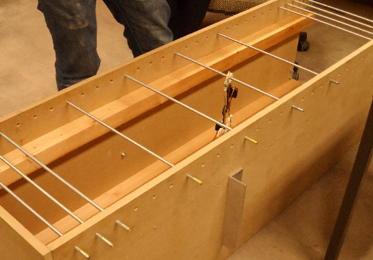
We decided to verify if the free arm can reach the next limb in a horizontal path of the previous limb (see Figure 5). This second step was done without the use of the gyroscopes but by timing; it is shown in the Video 2 below.
In Video 2, we observed at the first test that the free arm almost reached the next limb at the end of its swing,
but it revealed not to be a success at the second test.
In conclusion, it was a fail. The reasons of this fail could be explained by the following:
- The robot was very light so that the bending due to the wires could disturb the motion behaviour.
- Some short circuits could happen because the "naked wire" can touch each others.
- During the swing, transverse swings appeared therefore a part of the total energy at the initial state was transmitted to the swinging crosses.
Third step
We decided to verify if the free arm can catch the next limb. After the second step, the hacked servomotor had to be removed from the robot because it was broken due to several times of fall. This third step was done without the use of gyroscopes, but by tuning some parameters; it is shown in the Video 3 below.
We noticed that the third step was a success, but we had to incline the ladder in order to reach the next limb and so the limb could be caught by closing the gripper.
Fourth step
The fourth step which consists in verifying the previous step with our PCB instead of the ARDUINO board,
was a success as shown in the Video 4 below.
Fifth step
It consists in verifying the open/close grippers acting by means of the gyroscope with the ARDUINO board at the end of a swing. It was unreachable with our robot for a horizontal path. The reason of this fail is due to a problem with the wires of gyroscope. In fact, the wires always disconnected from the ARDUINO board during the swing due to their rigidity so that the microcontroller did not receive information on angles from the gyroscope sensors; thus, the robot goes crazy.
Final step
Because of the fail at the fifth step and two out of three servomotor were broken, the final step consisting in running the brachiation motion on a horizontal path could not be tested. We could also not perform multiple brachiations because of the broken servomotor of the gripper.
2. Further improvements
- To perform autonomous brachiation on many limbs at the same level height as well as higher height as shown in the Videos 5 and 6 below which were simulated.
- To use less rigid wires.
- To use metal gearbox servomotor in order to avoid break out.
- To find a way to avoid the swinging crosses and the bending due to the wires.