TEAM1 - Project - Brachiationbot - 2012-2013
ELECTRONICS and PROGRAMMING
On this section, you will find :
Firstly, the electronics which is split into 2 subsections :
- the electronic components corresponding to the internal functions.
- the PCB design.
Finally, the programming.
All the datasheets can be downloaded here.
All the PCB design on Eagle can be downloaded here.
The software implemented on the PCB can be downloaded here.
1. Electronics
1.1. Electronic components for controlled functions
The table below shows you the type of servomotor and sensor which were chosen with respect to the requirements from the specifications section.
| External functions | Requirements | Internal functions |
|---|---|---|
| Open/close gripper | 600 [°/sec] to open/close | Servomotor HS-81 + STMicroelectronics LY3100ALH (gyroscope) |
| Rotation between two legs | Speed > 80 rpm + torque > 0.0231N.m | Hacked servomotor HS-81 |
One of three of servomotor had to be hacked because the rotation between two arms demanded a continuous rotation.
Since the resistant torque necessary for the grippers were less than the maximum torque provided by the main servomotor and
since the servo's speed was enough and the price wass reasonable, we decided to choose the same servomotor for the grippers.
1.2. PCB Design
We decided to make three PCB; one called "main PCB", where we put the microcontroller ATMEGA328P-PUPTH and the power supply circuit, and the two other called "complementary PCB", where we put the gyroscope. These two "complementary PCB" will be connected to the "main PCB" by mean of a four pin dual-female jumper wire cable.
1.2.1 Main PCB
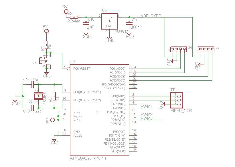
Before making and using our PCB, we used the ARDUINO UNO microcontroller board based on the ATMEGA328P-PUPTH. This type of microcontroller was removed from the ARDUINO UNO board and was placed onto our PCB. The Figure 1 below represents the PCB schematic of microcontroller on Eagle.
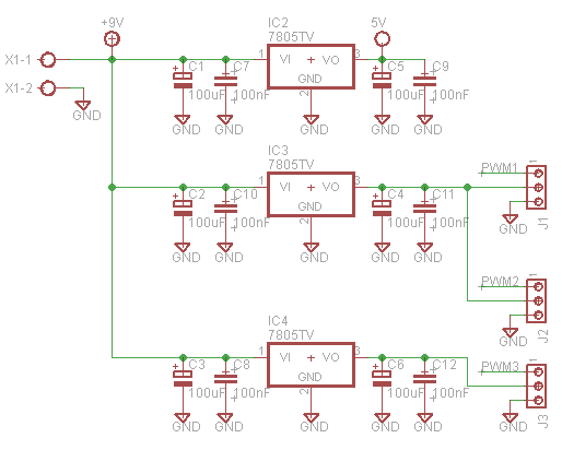
There were three power supply circuits; one for the microcontroller where a voltage regulator circuit was used to create 5V output, another one for the rotation between two arms which demanded a voltage output of 6V and a high current in order to defeat the resistant torque, and the last one for the grippers which demanded a voltage of 6V and a less current due to the less resistant torque. Also, the presence of PWM components allowed us to get a control of the angular speed of servomotors. The Figure 2 below represents the PCB schematic of power supply on Eagle.
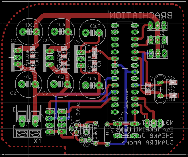
We then proceed to design the "main PCB" layout as shown the Figure 3 below.
1.2.2 Complementary PCB
For the reasons of simple, light, and fashion mechanical structure, we decided to stick a gyroscope with its PCB support on each arm while the "main PCB" was not put on the brachiation robot. The angle values of two arms given by the gyroscopes were transmitted to the "main PCB" by mean of the four pin dual-female jumper wire cable so that the microcontroller could act the open/close of the grippers. The Figure 4 below represents the PCB schematic of the gyroscope on Eagle.

We then proceed to design the "complementary PCB" layout as shown the Figure 5 below.

1.2.3 Electronic Components List
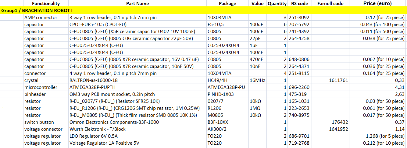
The Figure 6 below show all electronic components used in this project including the package, the price, value, and so on.
2. Programming
2.1 Aim of the software
The aim of the robot is to be able to swing from limb to limb. It has to be able to hold a limb with one hand while the other hand tries to catch the next limb. The catch function consists in openning/closing the gripper. Moreover, the manner to swing from limb to limb is important.
2.2 Procedure
The Figure 7 below represents the diagram of the robot system in which the principal functions are represented by blocks connected by lines.
We assume in this figure that the catching of the next limb will be done in only one swing.
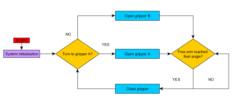
The working principle of the robot is described by the following steps:
-
START
The robot is switched on. -
SYSTEM INITIALIZATION
The robot is configured to a default state and we set up the I/O. -
TURN TO GRIPPER A?
The time for gripper A to open is checked. If it is effectivily turn to the gipper A, it will open otherwise the gripper B will open. The switch is verified by a counter. -
FREE ARM REACHED FINAL ANGLE?
When one of the gripper is open, the read of the gyroscope sensor starts. If the value transmitted by the gyroscope of the free arm reaches the final angle, the limb can be caught so the servomotor between the two arms will stop and the gripper will receive a close command; otherwise, the robot is still swinging and the read of the sensor is continually tracking until the wish value. -
LOOP
Once the gripper is closed, we go back to the step 1 but the difference is that the turn to the second gripper to be actioned.
2.3 Code
The main outline of the code is described below:
-
void setup()
This function which is called in the main function, consists in initializing the system (to set all variables with a default value and to set up the input/output pins). -
void loop()
This is the main function in which we find the schema block in the implemented form. -
void gripper(int numGripper,int action)
This function which is called in the main function, consists in commanding the action of the considered gripper. The parameters sent to the functions are the gripper's number and the action (close or open). -
void rotation()
This function which is called in the main function, consists in controlling the rotation of the servomotor between the two arms. -
void gyroscope()
This function which is called in the main function, consists in reading the angle of the two arms. -
void acceleration(int initialSpeed,int finalSpeed,int increment)
This function which is called in the main function, consists in accelerateing/decelerating the servomotor between the two arms. The parameters sent to the function are the initial speed, the final speed, and the increment. The last one is positive in case of acceleration and negative in case of deceleration.
The implementation of our software on the PCB was done by means of the ARDUINO board, USB cable, and the ARDUINO software.