


In this section, the design of our robot will be described. We will start by explaining the theoretical design, made using the CATIA CAD software. The three main parts of the robot will be described: the grippers, the arms, and the central articulation. Then, the problems we encountered will be exposed, and the design modifications required to make our robot work will be detailed.
Theoretical Design
Originally, the design of our robot was the following:
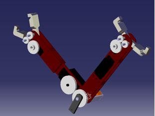
General Overview:
The robot is composed of two simple arms, rotating relatively to each other. Two grippers are operated using small gears and servos. Originally, the relative rotation of the arms (central articulation) was supposed to use the MACCEPA mechanism, allowing a far better compliance than a rigid joint. The MACCEPA mechanism uses two servo motors: one is used to position the lever arm to which a spring is attached; the other is used to set the pre tension of the spring, and therefore adjust the compliance.
Two sensors were planned to be used: a potentiometer, placed on the central rotation axis, and used to measure the relative angle between the two arms, and a gyroscope, placed on one of the arms, used to measure to absolute angle of this arm. Using both sensors, the absolute position of both arms could be known.
The main parts of the robot will now be further detailed.
The Grippers:
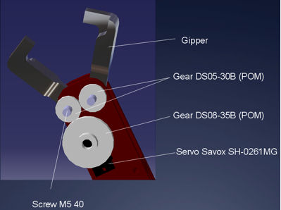
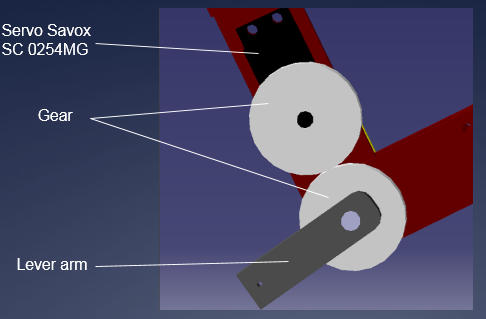
The grippers were designed to be printed using the 3D plastic printer. On their rotation axis, plastic spur gears would be fixed, and a small servo motor would make them rotate, using a third spur gear. Since the gears were purchased directly on the RS website, they were not created in detail in the CATIA software: only their radius mattered.
This image shows the grippers in more details, specifying the serial number of the gears and servo motors we used.
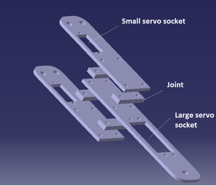
The Arms:
The arms were designed to be created using a laser cutting machine. Plexiglas was chosen, because it was both light and robust. Since the laser cutting machine only allowed thickness up to 4 mm, several Plexiglas joints were designed, in order to reach the desired arm thickness. The sockets for the servo motors and the screws were included in the original design, to avoid further drilling.

The Central Articulation:
The central articulation uses two gears. One of these gears is placed on a servo motor, and is used to make the other one rotate, thus placing the lever arm at the desired position. A spring is connected to the lever arm, and to another servo motor, used to set the pre tension of the spring. The rotation axis simply consists of a screw.
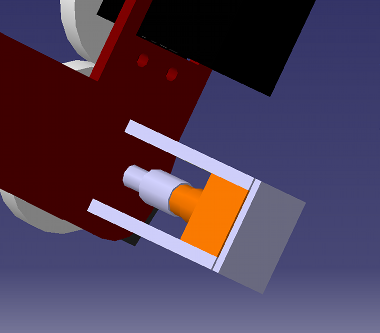
At the other side of the articulation, the potentiometer is placed. This potentiometer has been chosen to possess low friction, because we did not want it to cause too many losses when rotating. The rotation axis of the potentiometer is fixed to the central rotation axis, itself fixed to one of the arms. The fixed part of the potentiometer is fixed to the other arm, using the small Plexiglas plated shown in this picture:
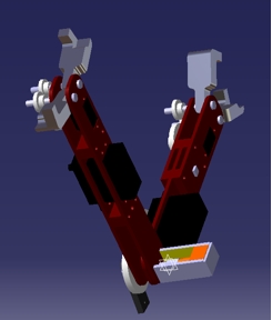
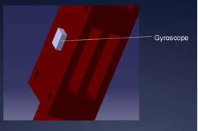
The accelerometer can also be observed on the arm:
The PCB Location:
At first, the PCB was not supposed to be on the robot, which would have required to create two PCBs, one of which would only have contained the accelerometer which had to be on the arms. After many considerations, it was decided to create only one PCB, and to put it directly on the robot.

Encountered Problems
Play between the Gears:
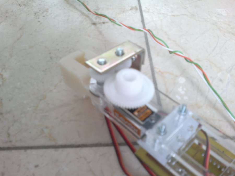
Our first main problem was that the tolerance of the laser cutting machine was higher than expected, leading to non negligible play between the gears of the grippers. The grippers could simply not be controlled. To solve this problem, small metal plates were fixed to the arms and surrounding the gears, leading to an almost perfect fit, as illustrated on the picture below.
Play also occurred between the gears of the central articulation, but a lower scale, which allowed the problem to be solved more simply, by adding some nuts to the fixation mechanism.
The MACCEPA Mechanism:
Although a very nice idea in theory, the Maccepa mechanism was too complicated to implement correctly in the time frame that was imposed to us. After several days of inconclusive testing, the group was forced to admit this mechanism would not work, for the following reasons:
- The mass was too high (two servo motors, levers arm, additional screws and nuts, etc.) - The mechanism did not react quickly enough and was not controllable easily enough.
These videos illustrate the functioning of our first robot, using the Maccepa mechanism. The separated mechanisms were working, but the brachiation movement could not be achieved.
Grippers:
Lever arm:
Pre tension:
Final Choices
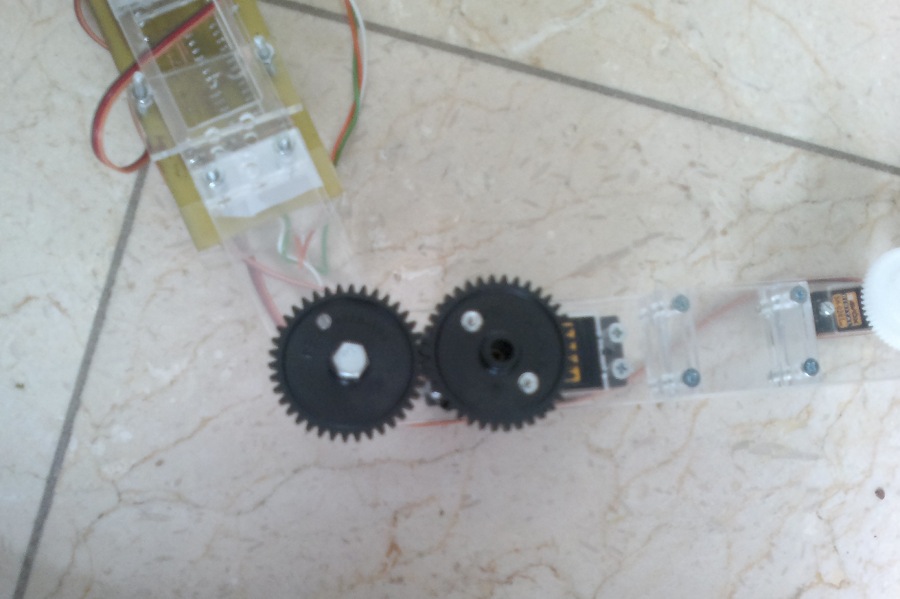
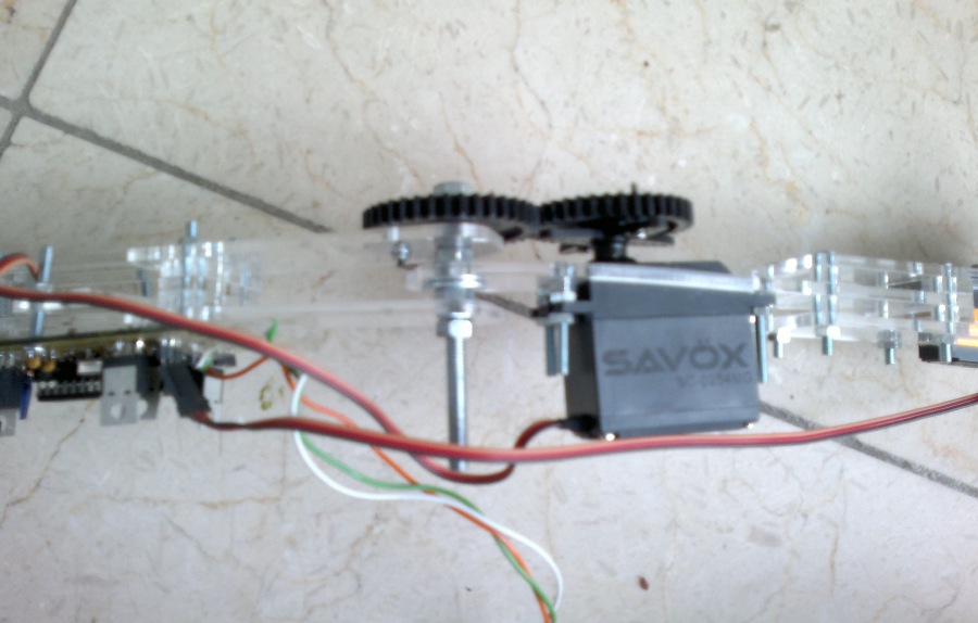
This is why the group decided to move to a more traditional solution: a rigid articulation. In this new configuration, only one central servo motor was needed, and was directly linked to the other arm. Indeed, one of the gears was fixed directly to the servo and therefore to the arm (just as before), but the other gear was fixed to the other arm using a screw (whereas before it was free of rotating relatively to the arm). This solution also allowed suppressing the need for an external potentiometer, since the servo motor already contains one, and its rotation is directly linked to the one of the arms.
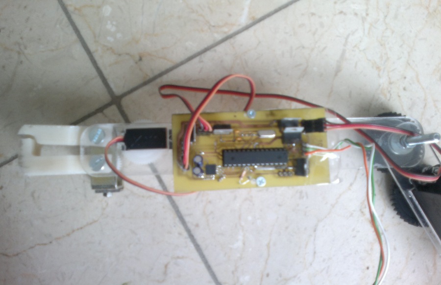
This new mechanism is illustrated on this picture:
The whole finished robot is shown of this picture:
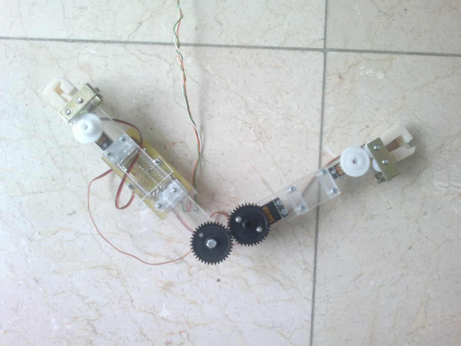
This new mechanism allowed us to reach our objective: the robot was able to perform a brachiation movement (see Completion).
As regards the components that we bought:
- Small servos = 20.9 € (x2)
- Main servo = 27.5 € (x1)
- Small gears at the grippers = 2.47 € (x4)
- Medium gears = 3.35 € (x2)
- The large gears at the central articulation were provided by Mr Grosu at the lab.
- The accelerometer (MMA6813KW)=6.78 €(x1)
- The potentiometer (95A1D-Z28-EA0/303L) = 7,37 € (x1)
but because they were out of stock, the potentiometer was provided by the Mechatronics service.
All the CATIA files and .dxf files (used for the laser cutting) can be found here: Download CATIA and .dxf Files