Components and Hardware
The project uses three servo motors and one webcam
The plan motion is insured by 2 servomotors and a third servomotor is used to activate the gripper as stated before. A webcam is used to recognize the pieces and their positions.
Servomotors:
1- For the plan motion the following motors were used (imposed).
2- This servo controls the gripper. It was chosen because it has small weight and due to the small weight of the gripper, in addition the torque needed to control the gripper's arms is very small, we can turn it manually without effort, hence the torque is not a design factor. And should rotate at least 180 degree.
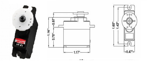
Specifications:
- Size: 1.2" x 0.5" x 1.2" (30mm x 12mm x 30mm)
- Weight: 0.58 oz (16.6 g)
- Torque 4.8V/6.0V: 36/42 oz-in (2.6/3.0 kg-cm)
- Speed 4.8V/6.0V: 0.11/0.09 second
- Bearing Type: None
- Motor Type: 3 Pole Ferrite
A servomotor has been used in order to activate the gripper because a precise rotation angle is needed; the gripper needs an angle range that is well defined. In addition back-drivability is very important; in fact the motor should be able to turn in both directions so that the gripping and releasing actions could be achieved. Also the servomotors are reliable and simple to control.
Webcam: the webcam that is used has a resolution of 0.3 megapixels. The resolution isn't an important factor in our case, because the colours of the board are black, white, red and green. These colours can be treated separately using filters and the board could be easily recognized. In the software part, a more in-depth explanation will be presented
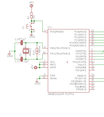
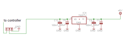
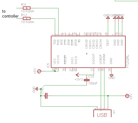
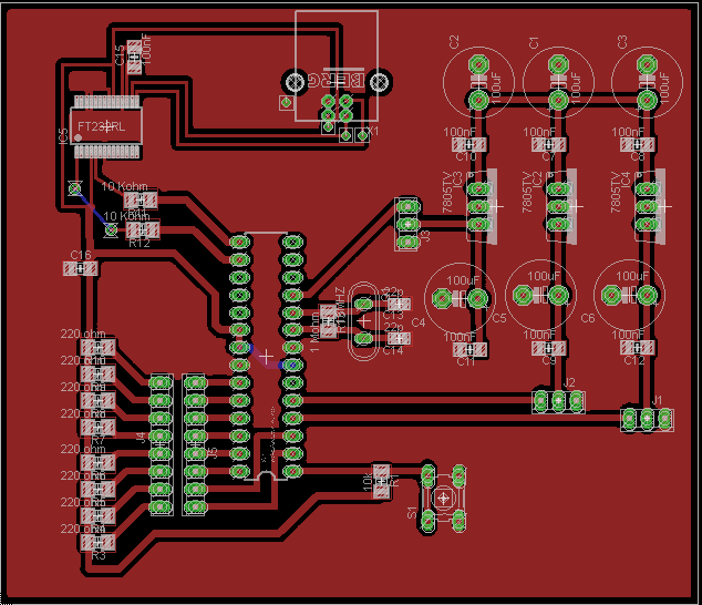
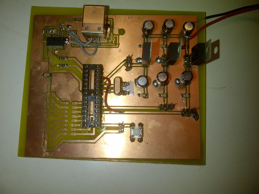
Microcontroller: To control all these elements an Arduino Uno board was used to make the tests, but for the final prototype a PCB was also designed and we used only the parts of the Arduino that we needed. In fact we only kept the features that were interesting in our case. Namely we kept the microprocessor, oscillating quartz of 16 MHz, voltage regulators to supply the motors, and a FT232 module equipped with a type B USB to ensure the constant communication between the Computer and the Microcontroller.