PCB Control
One of the goals of the project is to learn how to control the movement of our robot by controlling 3 servo motors and also to control two leds to give a good look and brightness. The transmission will be done via a Bluetooth module connected to the phone using a specific application. The control will be done by the Arduino.
Major components:
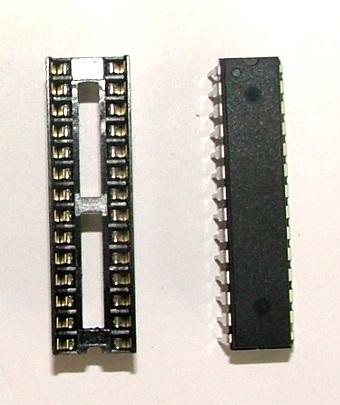
- 1. Microchip of the arduino 28-pins;
- 2. Bluetooth model;
- 3. Voltage regulator 5v;
The microchip needs a 16MHz oscillator in addition to two 22pF capacitors and a resistor of 10kΩ;
The voltage regulator needs two capacitors of 10μF;
The Bluetooth module doesn’t need any additional components;
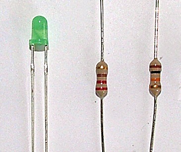
In addition to these components a led will be used to comfirm the current flow in the circuit. This led requires an extra 330Ω resistor when installed;.
Connections:
-
1. voltage supply pins:
-
2. Microchip:
-
3. Bluetooth model:
-
4. Voltage regulator:
2 headers will be installed within the PCB and they will supply it with voltage from the supplier;
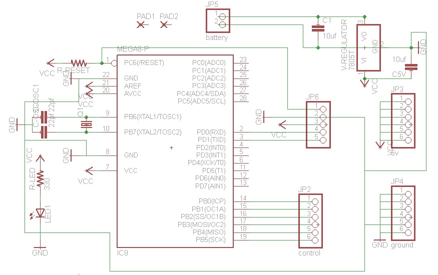
28 pins are available on the microchip, 16 of them will be used:
Pins 7, 20, 21 will be connected to 5v line;
Pins 8, 22 will be connected to the ground line;
Pins 2, 3 will be connected to the Bluetooth model for transfer and receive;
Pins 9, 10 will be connected to the 16 MHz oscillator and 22pf capacitors;
Pins 14, 15, 16, 17, 18, 19 will be connected to the motors and leds for control needs;
Pin 1 (reset) will be connected to 5v with a 10kΩ resistor in series and also it will be connected to a header in case there is need for programming the chip;
The reset button is not used in the PCB, because reset can be done by external cut of the current;
The Bluetooth model has 4 pins (translate/ receive/ ground/ VCC);
The translate pin of the Bluetooth model will be connected to the receive pin of the chip (pin 2);
The receive pin of the Bluetooth model will be connected to the translate pin of the chip (pin 3);
The ground pin will be connected to the ground line;
The VCC will be connected to the 5v line;
The voltage regulator has three pins (input voltage/ ground/ output voltage);
The input voltage pin will be connected to the pin of the positive voltage of the voltage supplier;
The ground pin will be connected to the pin of the ground of the voltage supplier, and from this pin the PCB will be supplied by the ground line;
The output voltage pin will supply the PCB with 5v line;
Two capacitors of 10μf will be connected in parallel with the voltage regulator, the first will be between input voltage pin and ground pin, while the second will be between output voltage pin and ground pin;
Components:
Components Units needed Ceramic capacitors 22pF for the oscillator 2 Electrolytic capacitors 10μf for the voltage regulator 2 Crystal 16MHz 1 Voltage regulator 5v 1 DIP sockets Solder tail 28-pin 0.3” 1 330Ω resistor for the led 1 10kΩ resistor for the chip reset 1 Green led 1 Headers for the Bluetooth model and for the power supply and for the reset --
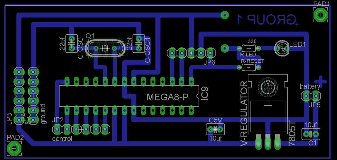
Layout
Eagle software was used to draw connections of the PCB and then translated them to a board layout. The best model was used to manufacture our PCB;