

Electronics:
The Arduino Uno microcontroller
The solenoid
The stepper motors
The time-setting device
To carry out this project, we had the choice between two microcontrollers: the Arduino Uno
and a PIC. Our choice went to the first one. Indeed, we thought we could benefit from its
user-friendliness as well as its numerous libraries. Moreover, since we already had the
occasion to work on a PIC during previous projects, this could allow us to build up new
experience.
The Arduino Uno R3 used is a small
microcontroller board based on the 8-bit chip
ATmega328. It possesses 14 digital I/O pins, 6
analog inputs as well as a serial port. It is possible
to program it through a standard USB bus. The
power supply may either come from the USB
connection, the power jack or a dedicated pin.


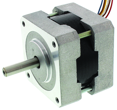
The first components we will review are the motors.
Why choosing steppers over servos? First, steppers are very intuitive to control, which gives
them an advantage over servos. Secondly, after leading researches on positioning systems,
it appeared that these motors were most often used for this purpose (DVD players, printers,
3D-printers…).
Operation
The principle of operation of steppers is fairly simple. A
current impulse on one of its terminals is converted into an
angular movement. The value of the angle (the step)
depends on the construction of the motor (read more
here). This allows for an effective open-loop control: there
is no need for sensors. We may know the position of the
motor by the number of pulses sent.
Choice of the motor
Several criteria were developed for the choice of the
stepper. The first one was the supply voltage. As our
power supply (see next section) provides 9V DC, we chose
not to exceed this value. Next, the torque was an
important factor. Although it was difficult to estimate the
needed torque, we chose the steppers with the highest
torque available. The two last criteria were the ease of
fixing to the case and, obviously, the cost. In the end,
among the RS range, we went for the 440-420 unipolar
stepper. It has a step angle of 1.8° (200 steps per
revolution), which is more than satisfying for our
application.
Control
There exist two types of stepper motors, with each one several ways to control them. Our
motor is unipolar (6 wires). Without going into detail now, the purpose of the control
system is to send enough current (much more than the Arduino can deliver) in the correct
sequence to the pins of the motor. We were then confronted to two options:
Although the first option would have saved us time and pins on the microcontroller, we
preferred to go with the second option to deeper understand the practical aspects of the
control. Once this choice made, we could begin the design. At first, we relied on the
explanations of this website (in French).
1. Use an existing all-in-one control chip (mostly designed for bipolar motors but usable
on unipolars).
2. Designing the control system with more elementary components, taking advantage
of the Stepper library.
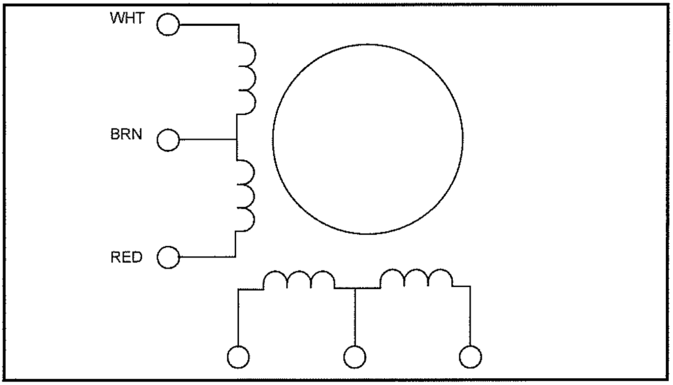
The unipolar stepper has six wires. As
showed on the image (extracted from
the datasheet), they can be seen as
the terminals and mid-points of the
coils. In order for the current to flow
through the windings successively, the
mid-points will be connected to a
constant voltage (5V, provided here by
a linear voltage regulator) and the
terminals will be put to 0V in the right
sequence, thanks to the chip described
in the next paragraph.
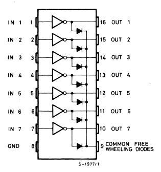
The chip used to power the motor is a Darlington
Array (ULN2003A). It is essentially a set of seven
transistors that provide the required current when
a chosen entry is put to the HIGH logical state.
The component chosen is rated for 500mA per
unit, which exactly suits the motor characteristics.
The layout for driving the motors is presented here in a Fritzing schematic (note that, in
practice, the circuit will be powered by an AC adapter and not by a 9V battery):
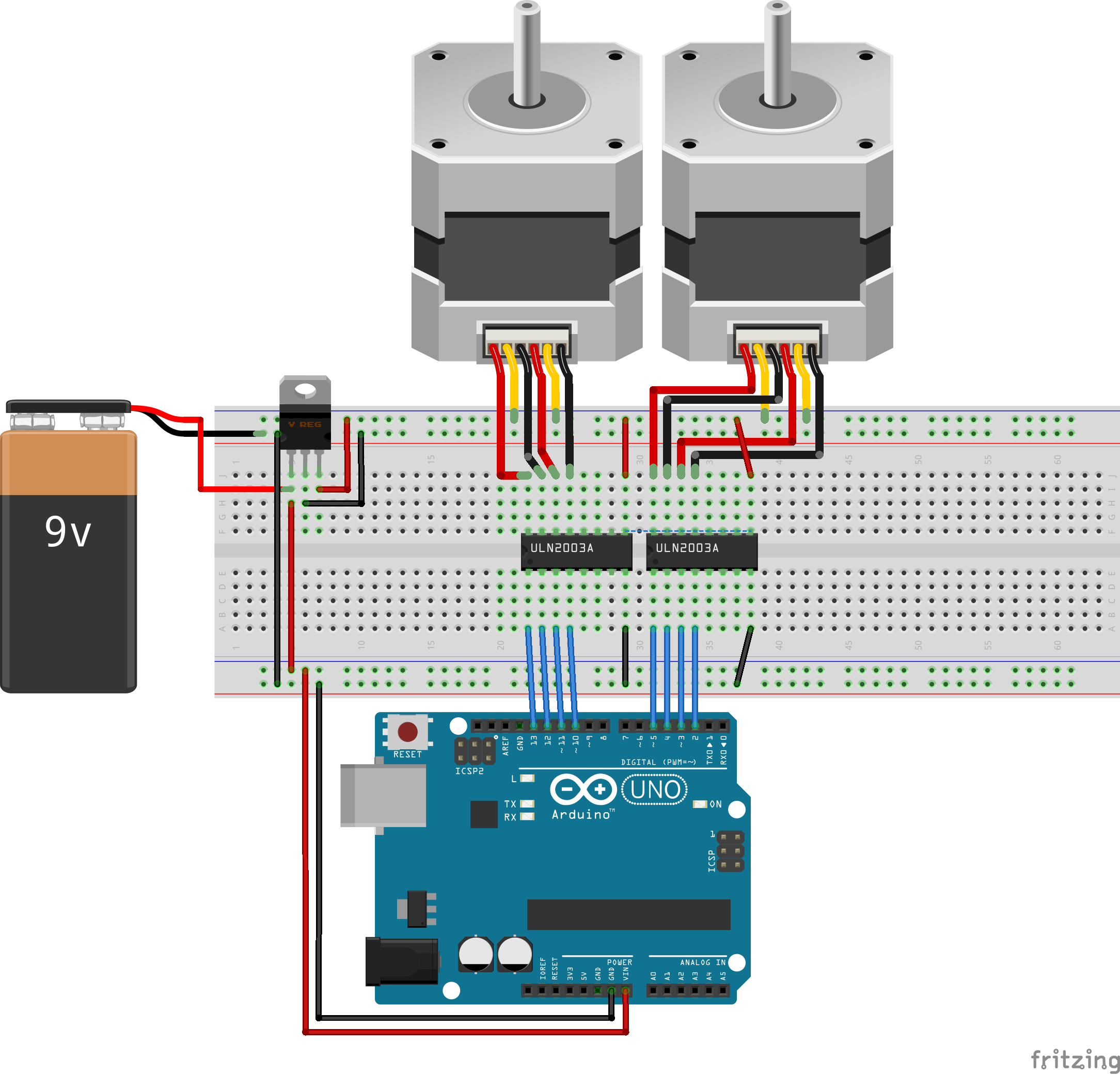
On this image, you can see that a total of eight pins is needed to control both motors. This
constitutes a problem since we will need 6 other ports for the other components (LEDs,
button and solenoid) and we wanted to keep at least one port free in case of design
changes. To solve this problem, two solutions were found:
-The first one allows us to control the two motors with four wires from the Arduino.
This is done by adding some connections and resistors between the pins of the
ULN2003A (schematic found here).
-The second solution we developed consisted in using demultiplexers to select which
motor we want to run. This can be done since the robot will write the time like a
digital clock, only one motor will be used at a time. This method of control thus
requires 5 pins: 4 for driving the motor and one for the selection. We chose this
method because it seemed more intuitive to us.
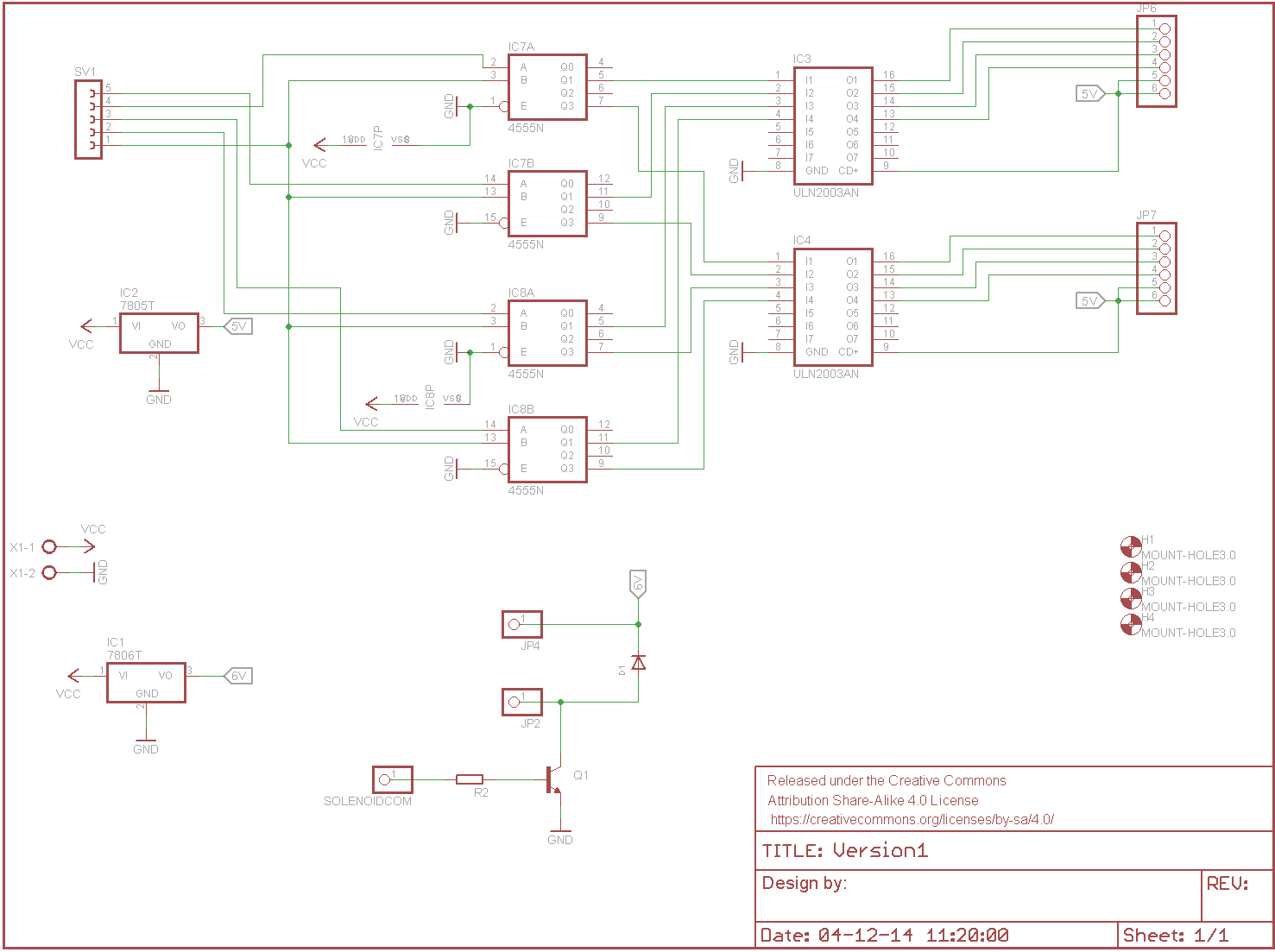
The final circuit for the steppers is the following:
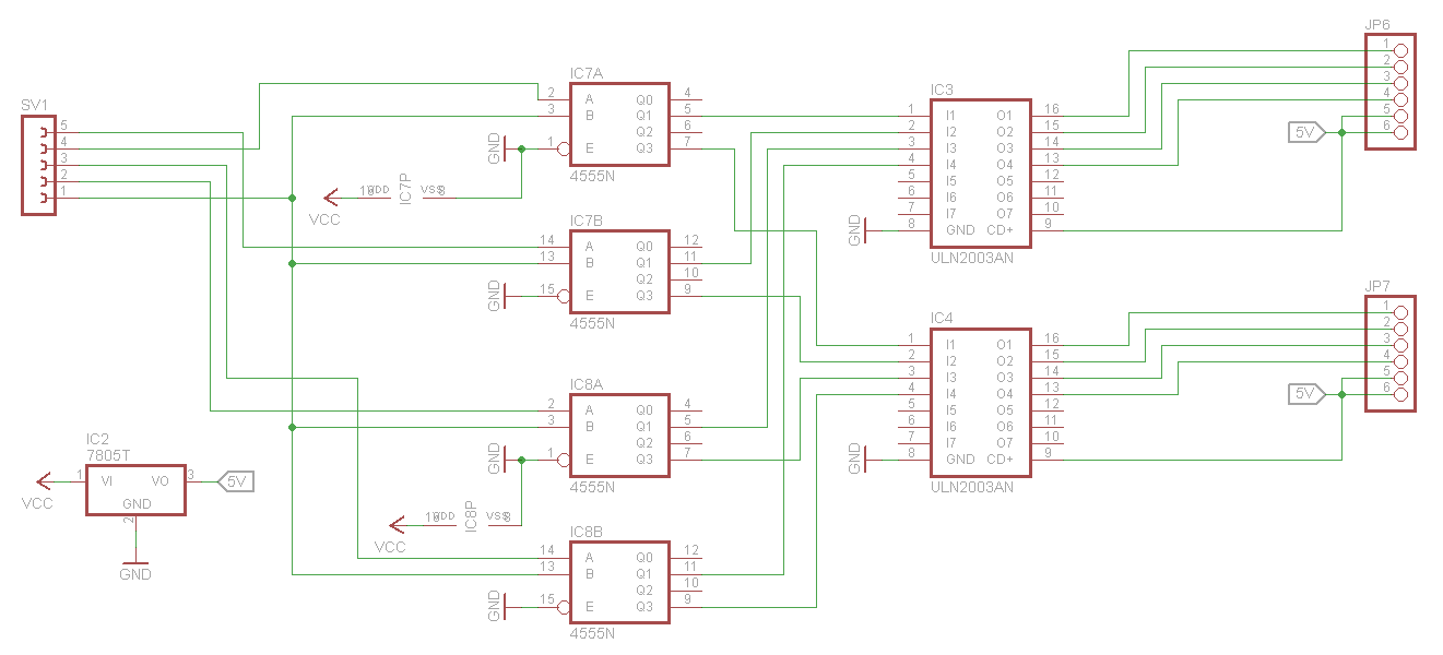
Click to open
The 5 pins on the left are the outputs of the Arduino while the two connectors on the right
are for the motors. The two 4555N chips are dual (2 in one package) 2-of-4 demultiplexers.
We only needed four 1-of-2 demultiplexers but none were available on the supplier’s
website. This is why some pins are not used.

Now that all major components have been chosen, it is time to choose a way to power
them. Let’s summarize:
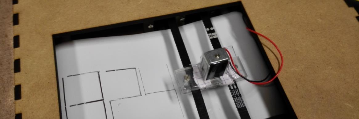
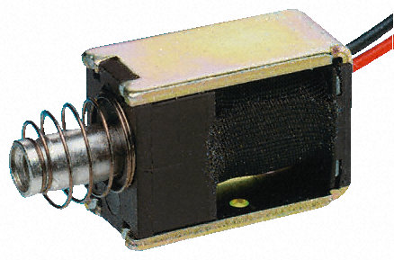
Choice of the solenoid
As the stepper motors take care of the positioning of the writing head, another device must
be added to perform the up-and-down movement of the tip. To achieve this, as explained
in the Mechanics part, we chose to use a solenoid. It is composed of two elements: a coil
and a metallic shaft. When a current flows through the coil, a magnetic field is created and
the shaft moves. There exists to types of solenoids: push-types and pull-types. The
difference is the direction towards which the shaft moves when the coil is energized. The
choice of the solenoid was guided by the following elements:
1. Supply voltage less than the power supply (9V): this
allows us to use a classic 78** chip to feed it.
2. Push-type: the solenoid is facing downwards; it
must then push the shaft in order to write.
3. Compact: it will be a mobile part, its dimensions
and weight should then be limited. We opted for the
only part available on RS with these characteristics: a
6V, 3W push solenoid.
Control
The control scheme used was found here. To put in in practice, we used the following
components:
-1A rated NPN transistor.
-1K resistor between the Arduino and the base of the transistor.
-1A rated rectifier diode.
While the NPN ensures that sufficient current is provided, the diode offers a way for the
current to flow when the transistor is closed and the coil has to discharge.

The power supply
-2 steppers, 0.5A each (though they are never driven
simultaneously).
-1 solenoid, 0.5A.
-Arduino, LEDs (see next section): maximum 0.5A
(estimated value with a safety margin).
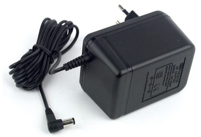
With this in mind, we searched for a standard AC adapter rated for at least 1,5A and 7V (to
be able to power the Arduino through the Vin pin). We found a 9V one with a maximum
current of 1,67A. As the steppers require 5V and the solenoid 6V, 7805 and 7806 voltage
regulators were ordered.

The Arduino Uno is not provided with any small battery that could track the evolution of the
time when it is not powered. Thus, we decided to design a system to input the time at the
start-up of the robot. It will then update the time until the robot is powered down. The
main challenge for this was to keep the number of pins needed small.
Our first idea was to use a LCD display, but the number of connections needed was too high.
With this in mind, we concluded that the best idea would be to use four LEDs that will
display a digit (0-9) in binary. The user sets the current minute using a potentiometer,
pushes a button to confirm, and proceeds like this for the four digits composing the time
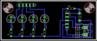
(Hh:Mm). The following circuitry was developed:
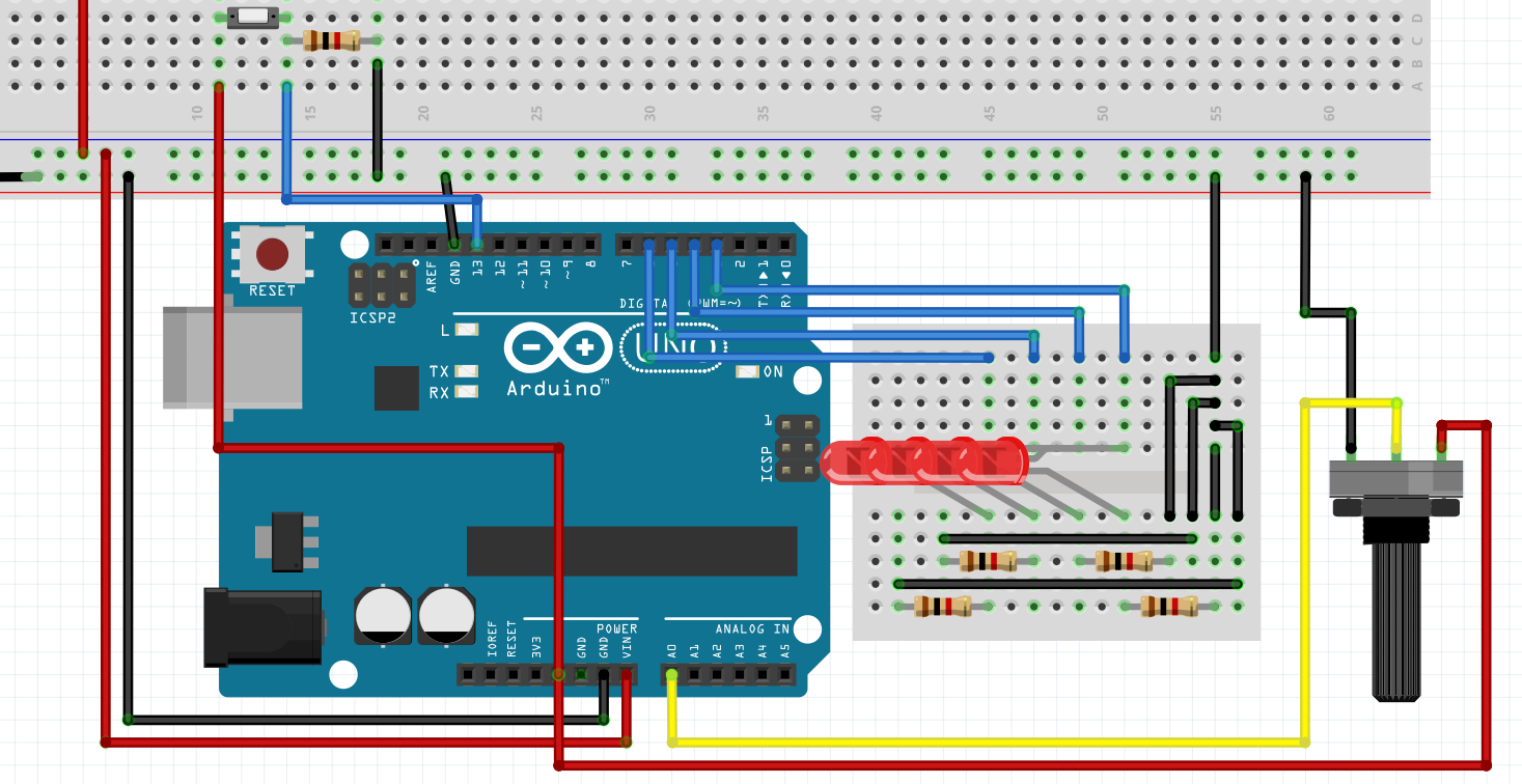
It is composed of four LEDs with their 330 Ohm resistors, a potentiometer and a push-
button with its pull-down resistor.

The PCBs
When all the electronic components were known, the design of the PCBs could begin:
-The first PCB will house the components for driving the steppers and the solenoid, as
well as two voltage regulators to power them.
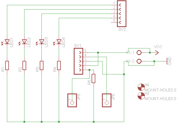
-The second PCB is for the LEDs and the potentiometer and button connectors.
The schematics and boards were developed in Eagle and are presented below. They are both
one-layer, so the main challenge was to keep them as compact as possible while maintaining
a good track width and a reasonable number of jumper wires.
Big PCB - Schematic
Click to open
Big PCB - Board

Small PCB - Schematic
Small PCB - Board
Click to open
Click to open
Click to open
