Assembly
The transformation from the CAD design to an actual working prosthesis, was not always straightforward. A lot of different parts had to be made on different machines and eventually assembled.
Gripper
The gripper is a relatively easy part to assemble. It consists mainly of 3D printed pieces. The most difficult part was to attach the gear to the servo motor. The hole was designed with the right diameter, but we quickly learned that the printed pieces always have a little bit smaller holes than how they were designed. To solve this, a bit of sanding was done to be able to fit the servo in. Afterwards, a bit of glue was used to make the connection stronger.
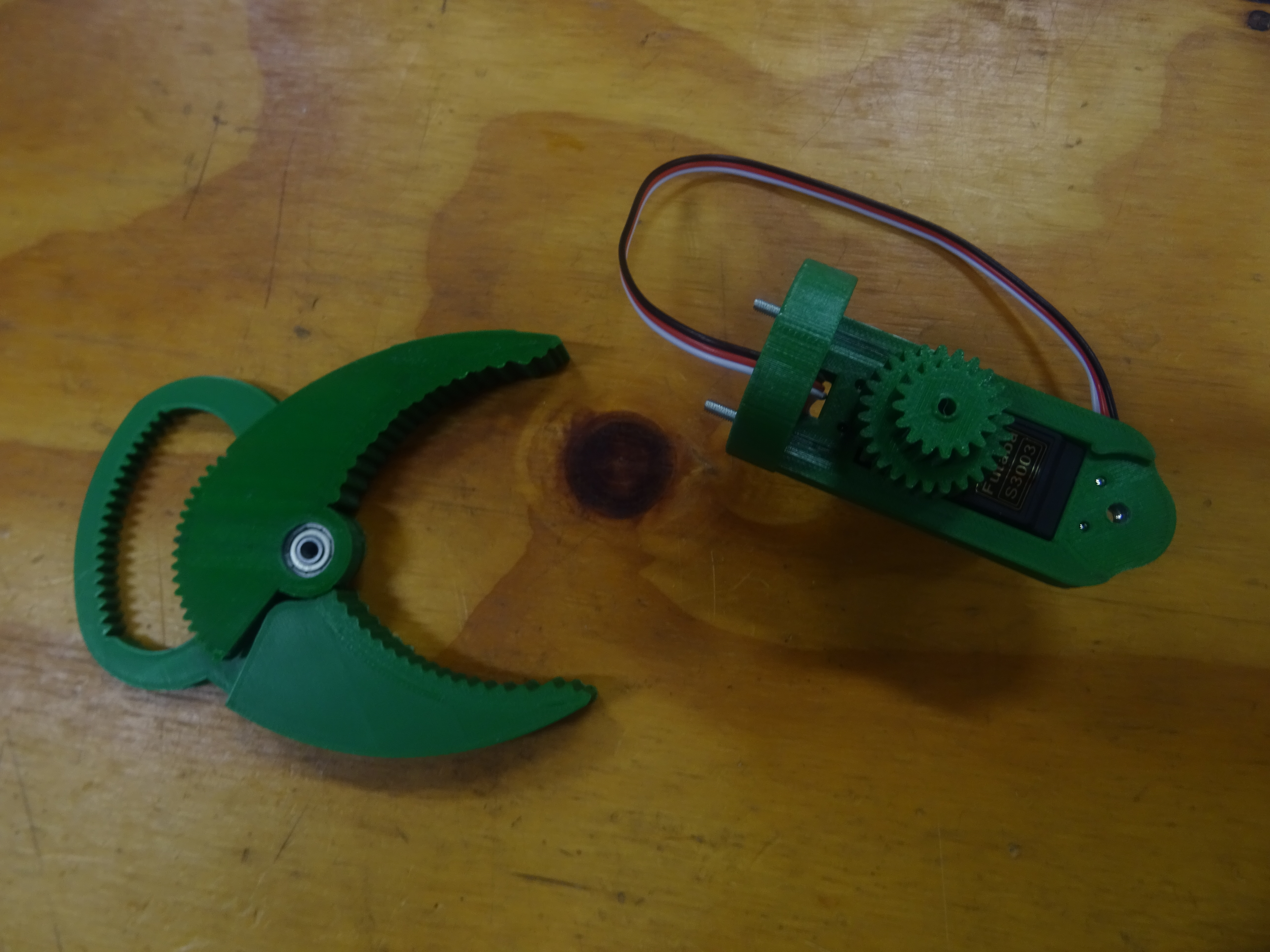
The parts of the gripper are ready for assembly
The two fingers of the gripper have bearings in them to minimize friction and optimize the alignment. They are aligned with each other and also with the servo mount in order to have a good connection between the gears.
Flexible arm
The flexible arm is made out of 40 cm of flexible hose, the tube is hollow, so the cables that feed the servo motor of the gripper can fit in. On the trunk, several equally spaced and aligned segments are present. The segments are made in plexiglass using a lasercutter and attached to the tube with glue.
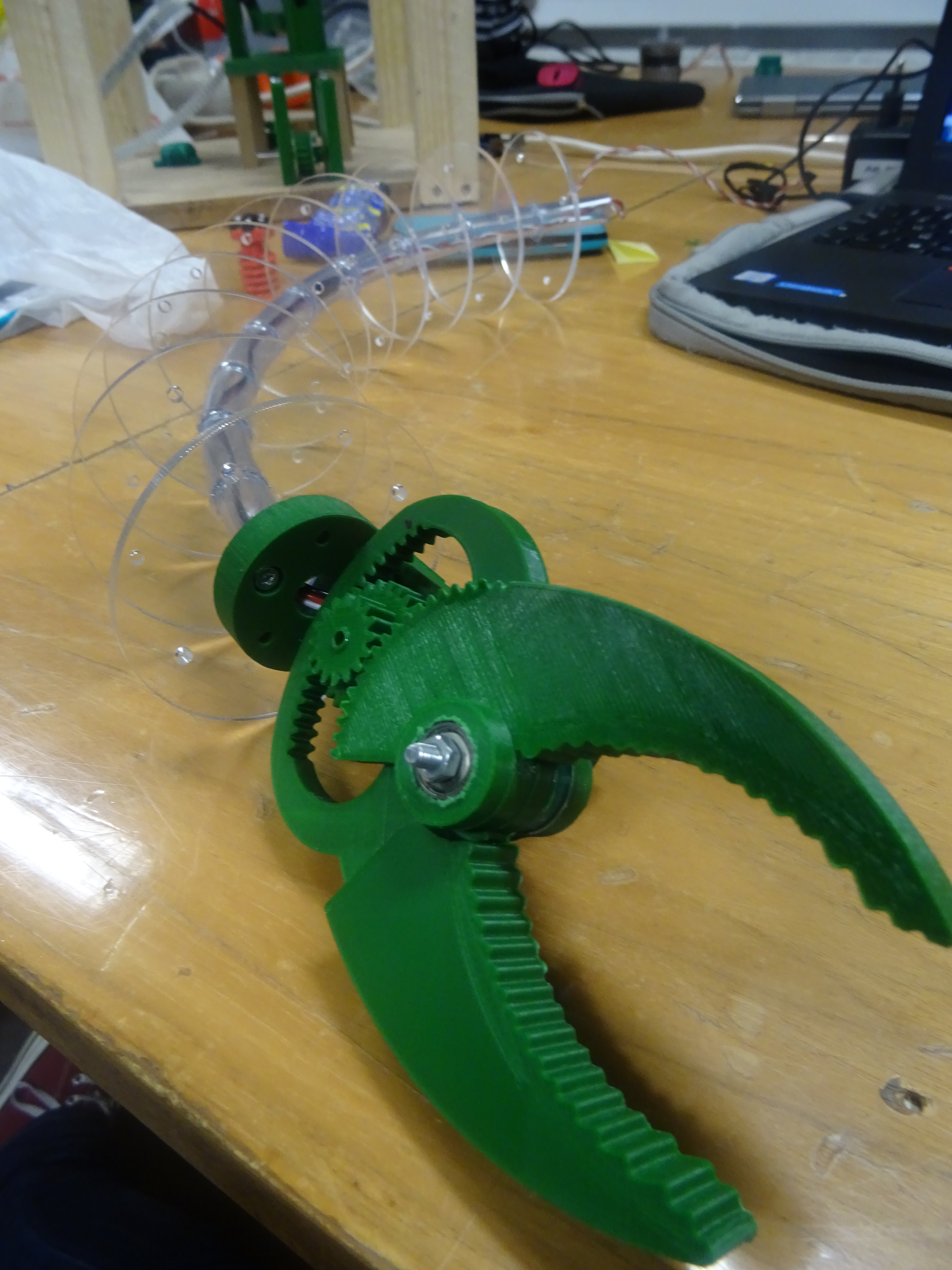
The gripper is connected to the arm
Case
The case holds all the components and is made as compact as possible, this is however not an easy task, as both transmissions should fit inside and the minimum size of the gears is limited by the accuracy of the 3D printers. The case has a simple box shape with some holes in it for different components to fit trough. It is again made out of plexiglass using a lasercutter, the fact that the box is transparent, since it allows to see what happens inside and to check if everything works as it should. Inside the box, all the different parts are assembled step by step.
Transmission
The first thing to assemble is an transmission. The first axis contains two spools for the wires and a gear. They are kept in place on the M6 threaded rod with washers and locking nuts. A potentiometer is connected with the M6 rod through a friction coupling. This allows to track the movement of the arm, as discussed earlier.
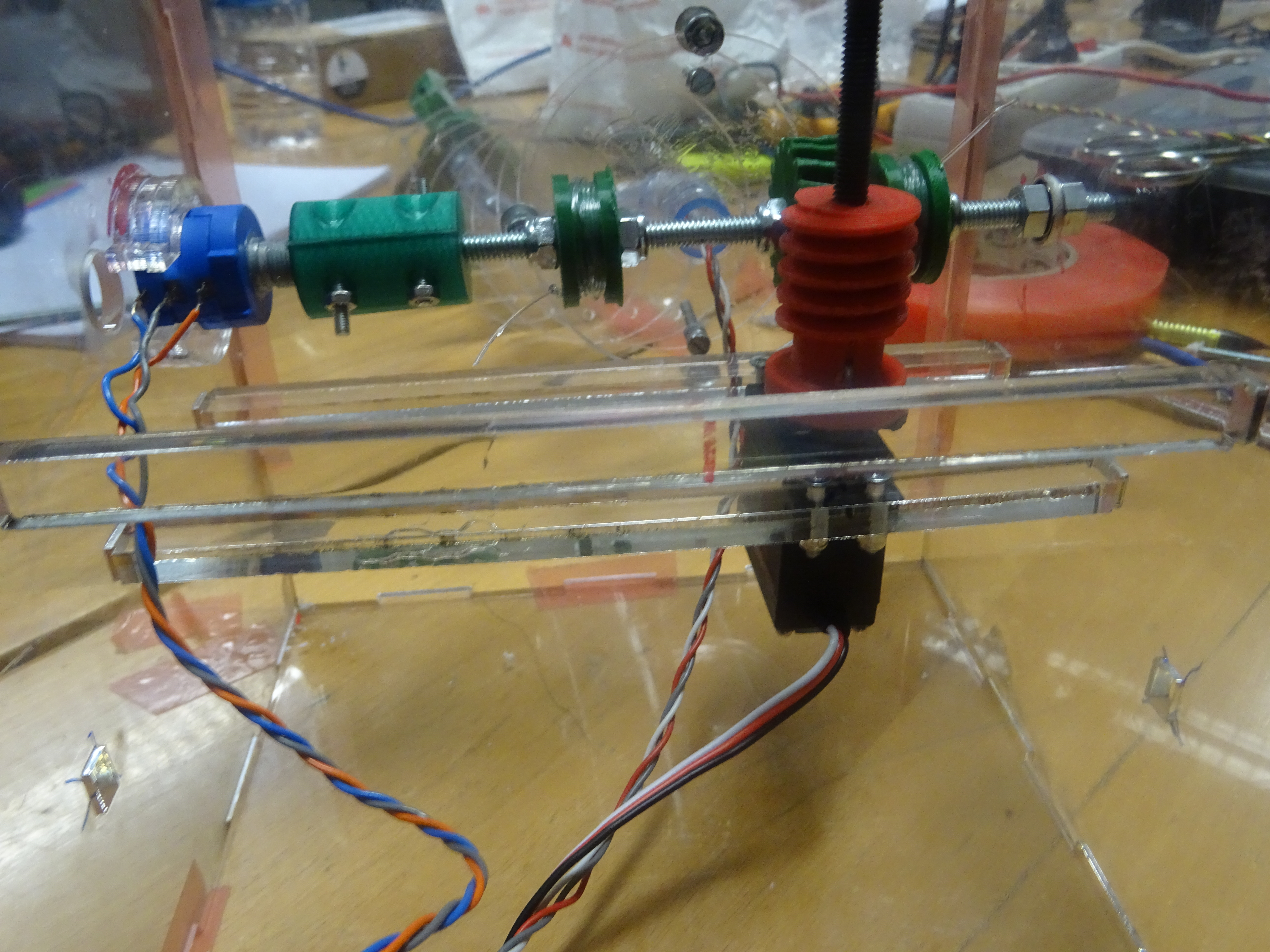
The first transmission is already assembled inside the case
The other axis contains the servo motor and the worm. Special care was taken to assure the perfect alignment of the gear and the worm. As the worm can not be printed without overhang, it was done while using support material on a printer with more accuracy.
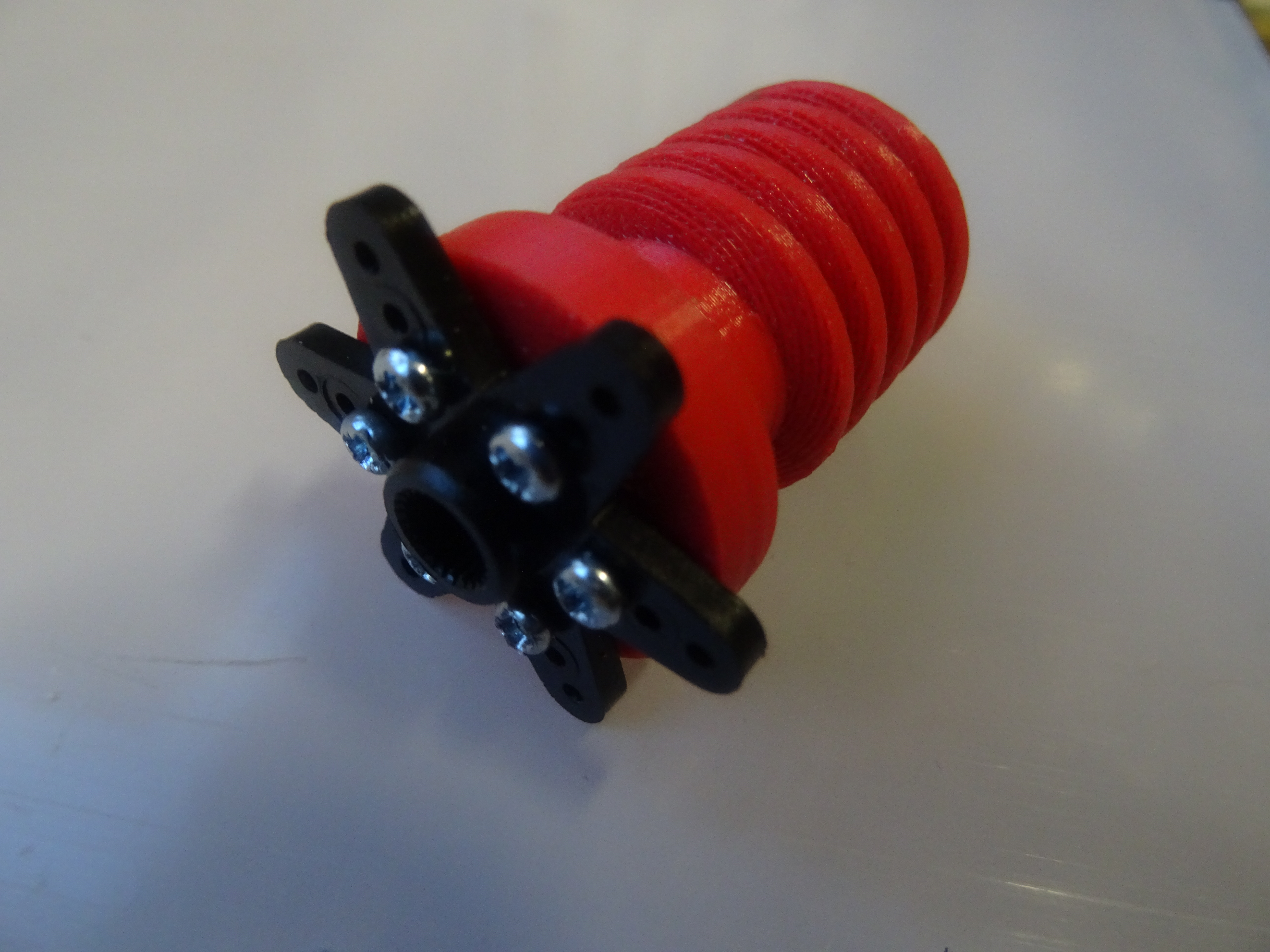
The connection between the motor and worm is sturdy enough to handle the torque
The connection to the servo is made with screws that fit through holes in the servo mounting piece and the worm itself. It needs to withstand a lot of forces, so an extra axis is used to keep the worm from moving too much horizontally and making the gear skip teeth.
Adding the wires
Concerning the application of the four wires to the assembly, they are one of the critical parts of the project. They should be capable to transmit the movement from the servos to the final segment near the gripper. The wires are first applied to the spools on the shaft of the servo, passing through the washers that are place around small holes in the first segment to fix the end of the rope.
The next step is to make the wires pass through all the segment thanks to predesigned small holes inside every segment. The final step is tension them in the correct way to give some extra stiffness to the whole structure and have a more reactive response during the movement of the arm. To obtain the correct level of tension, the movement of the shaft is blocked through a clamping system while the wire is manually pulled to obtain a good level of tension and in the meantime have enough sensibility to avoid to break the wire. Once the tension is reached, according to the properties of the ropes, the last part of this last step is to fix them to the structure thanks to a system of nodes, bolts and nuts.
Stiffness
After mounting the transmissions inside the case, the gear would still skip teeth when reaching a certain position. The cause of the problem was determined after some inspection, namely that the axes were not stiff enough. Due to this, the gear and the worm could move just enough to no longer make any contact. This problem was solved by adding some more stiff elements to the case and change the mounting position of the worm axis, so it is pushed harder against the gear.
Those extra elements were drawn in inventor, printed, and added to the assembly without too much hassle.
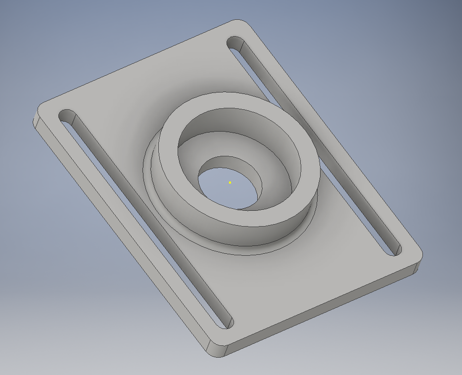
The stiffness was improved significantly by using two of these pieces inside the box
Electronics
The last part to assemble inside the case, is the electronics. All wires are neatly taped to the sides and the PCB was attached by using special plastic mounting pieces.
Testing
The total assembly can be tested when the assembly is finished. Therefore, it is mounted on a metal frame and connected to the power supply. This power supply is set to 7.2V as the PCB is designed for this voltage. It is also a standard voltage for batteries, which is useful as later on the prosthesis would need to work on a battery.
Several tests were done with the arm, such as moving the arm to the limits and see if the intended behaviour is obtained or grabbing and moving objects. All tests were sucessful, with the only remark being that the movements are rather slow.