Mechanics
The inspiration of the mechanical arm comes from the trunk of an elephant. It has excellent flexibility, good adaptability to unstructured and highly congested environment. It can not only grasp or grip things with the gripper attached at the end of the arm, but also grasp things using its whole arm. A rope-driven schematic is proposed that includes three main parts: the flexible arm, the transmission box and a gripper.
The main reason why this model of prosthesis may be desired, is because some models of modern prosthetics are part of the uncanny valley. This means that the prosthesis seems to replicate a human arm, but not exactly, making them undesired for some people.
Flexible arm
The flexible arm is based on the trunk design of the robot Probo. It consists of a flexible tube with several stiff segments. Through the stiff segments go four wires, they are installed in two pairs with opposed position: two for the x-direction and two for the y-direction. It could theoretically also work with three wires, but that would only complicate the design.
When looking at one direction, if a wire is shortened by pulling and the other one elongated, the arm will bend in the direction of the shorter wire. This concept still holds when using both directions, and a combination of x and y allows the arm to also move diagonally.
The tube is applied to keep the geometry between the different segments and is hollow so wires can get through. Those are needed to make it possible to control the gripper by providing its power.
The stiff segments are glued on the flexible tube
Transmission system
The main idea for converting the motion of the servo motors onto the wires, is to use spools. These will unroll or roll up the wires depending on the direction of motion of the arm. The arm will have one servo, one transmission and two spools for every planar movement. Because there are two degrees of freedom in the arm’s motion, two of the described systems will be required.
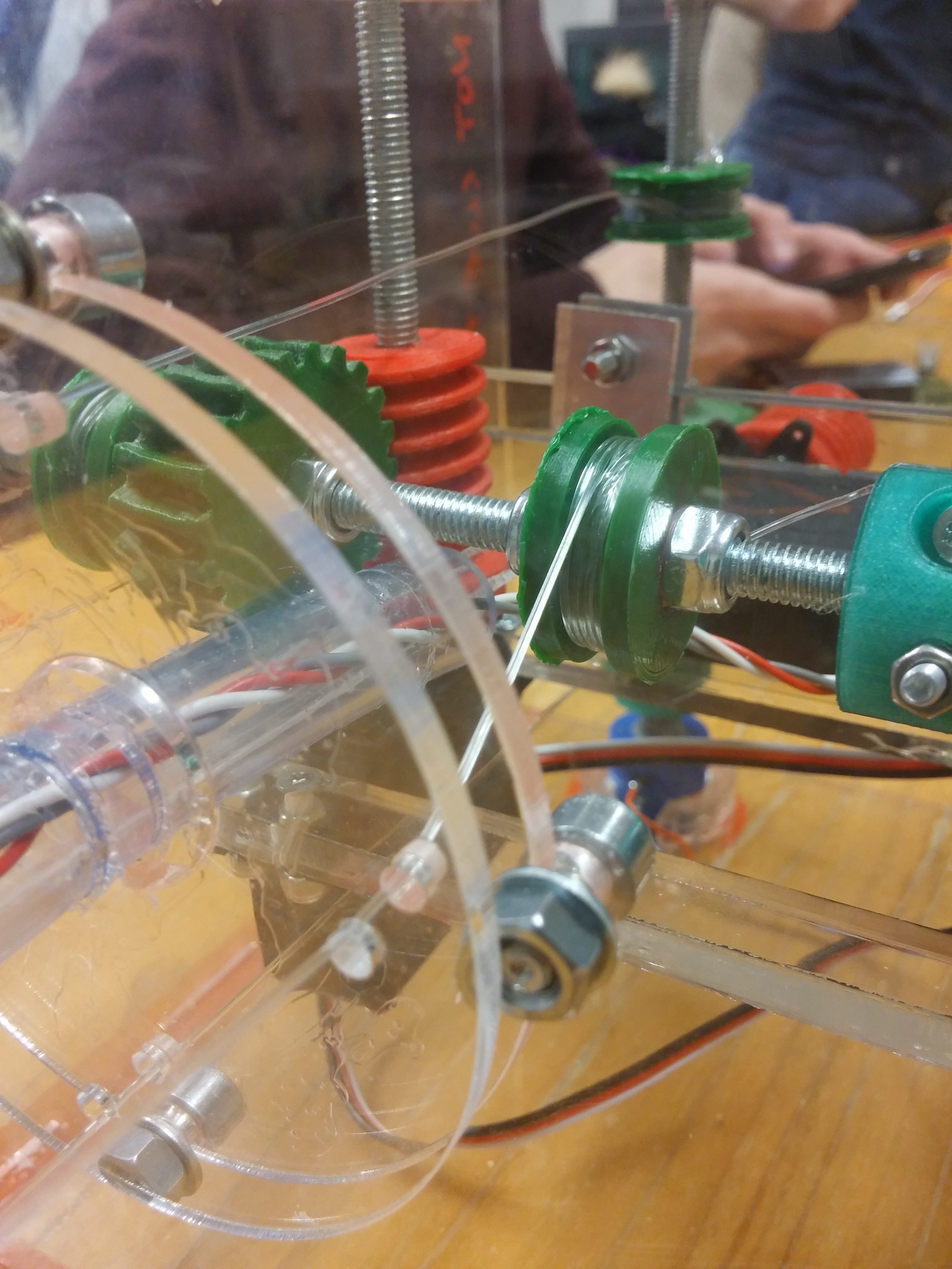
One system consists of a threaded shaft (M6) which carries two spools and a gear. To restrict the movement of the objects on the shaft, locking nuts were used. The gear will be set in motion by a worm gear which is connected to the actuator (in this case a servo motor). Because of the protection of the actuator, the choice of a worm gear can be justified. This is because an external force on the shaft should not be transferred to the servo motor and this is achieved by a worm gear.
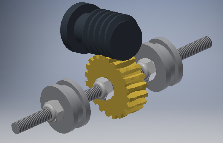
The transmission as designed in Inventor
If both transmission systems are put together, the arm can make all the necessary movements. To do this, bearings have to hold the two M6 threaded shafts in place. One side of every system will be connected to a surrounding case (see assembly) using bearings, the other side will be attached to a potentiometer to track the shaft’s rotations. The potentiometers will be fixed inside the case using laser cut pieces, which are glued inside the case. These pieces surround the potentiometer thightly and ensure that the potentiometers stay at the correct place. The whole system together is quite complex, it is therefore essential to perform the correct chronological steps in the final assembly.
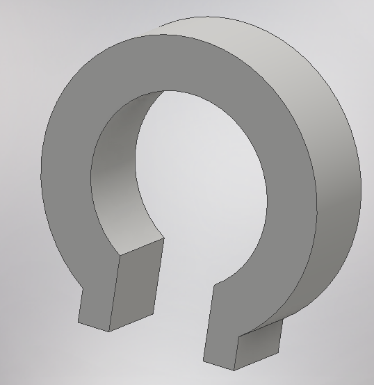
The potentiometer is kept in its position by a lasercut piece
Worm gear
For economical reasons, it is worth mentioning that the gears were 3D printed. This meant that the connections were not ideal. When testing the transmission, there were some issues with the worm wheel. Because of the load, the worm wheel made a precession in stead of an ideal rotation. This caused the transmission to skip gears. To solve this problem, a hole was drilled inside the worm wheel. Then a hole was drilled in the case to fix a bearing. Finally, a shaft was added in the worm wheel to keep it from skipping gears. When testing this system, it gave the necessary positive results.
There is only one downside of the printed gears, which is the fact that they are made of a plastic material. This material is not as strong as a metallic material. Also after long-term usage, erosion of the wheel will appear. This will therefore garantee future failure. So if this product was to be remade for consumption purposes, a material study will provide a more viable, long-term solution. In the case of a prototype, as is the case in this project, the plastic material will give a more economical and practical solution.
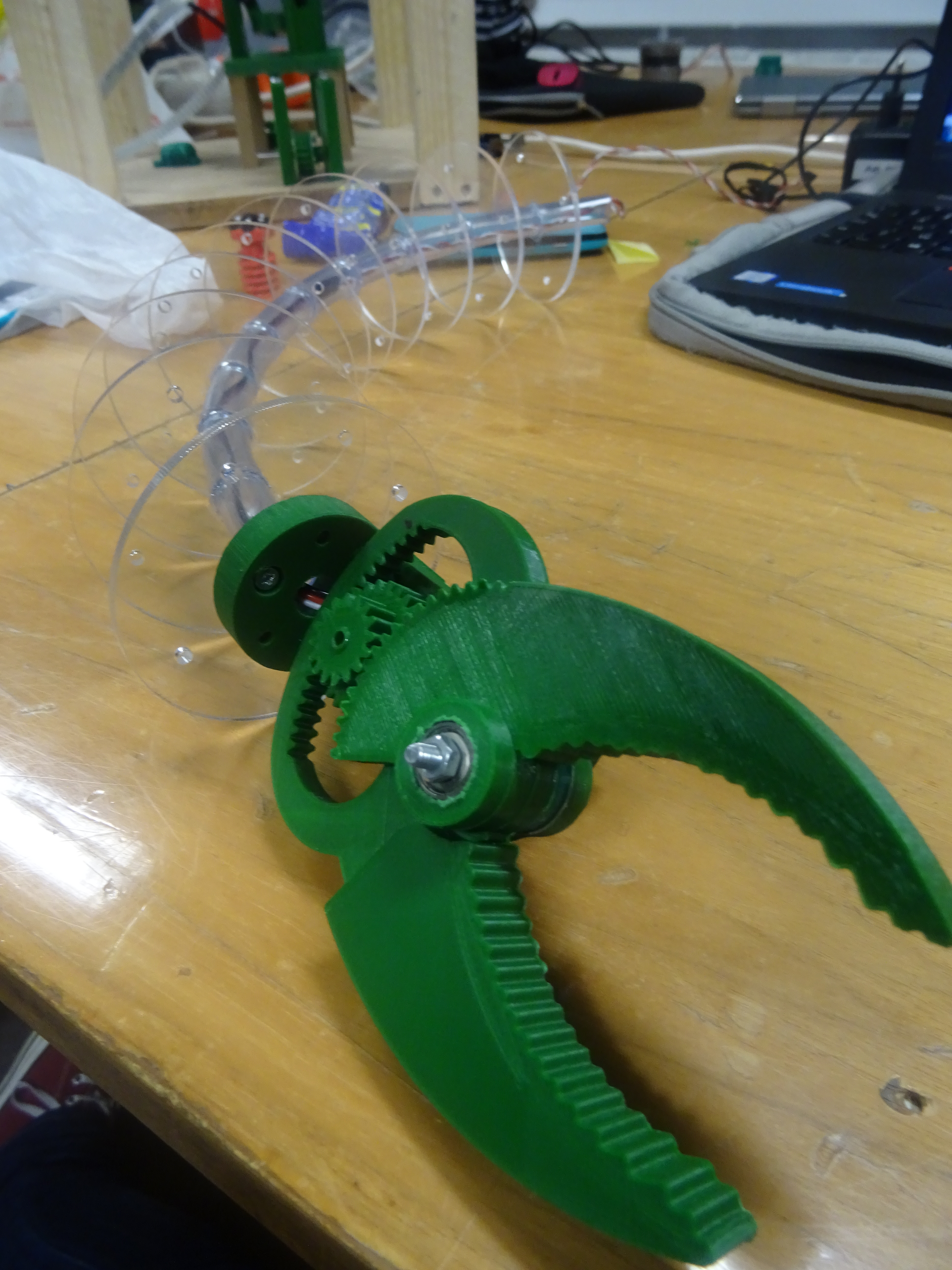
Gripper
For the gripper, the choice was made to start from an existing gripper and adapt it to fit the arm. The gripper that was chosen, was found on Thingiverse. This gripper was adapted to no longer use the urethane, fit the available screws, servo and segments. An other advantage of using this gripper, is that the different parts are already optimised for 3D printing, so no big overhang or unnecessary curvature is present.
A servo motor is used to drive the gripper. It is put at the end of the arm to simplify the transmission system. Wires pass through the tube and connect with the PCB which is installed in the transmission box. The servo can rotate 180°, one end of its range corresponds to a closed gripper, while the other end corresponds to the opened position. The opening and closing is done via a gear system that consists of a gear and two racks. The servo drives the gear directly. This gear is a double spur gear, each side drives one of the ‘fingers’ of the gripper via a rack.
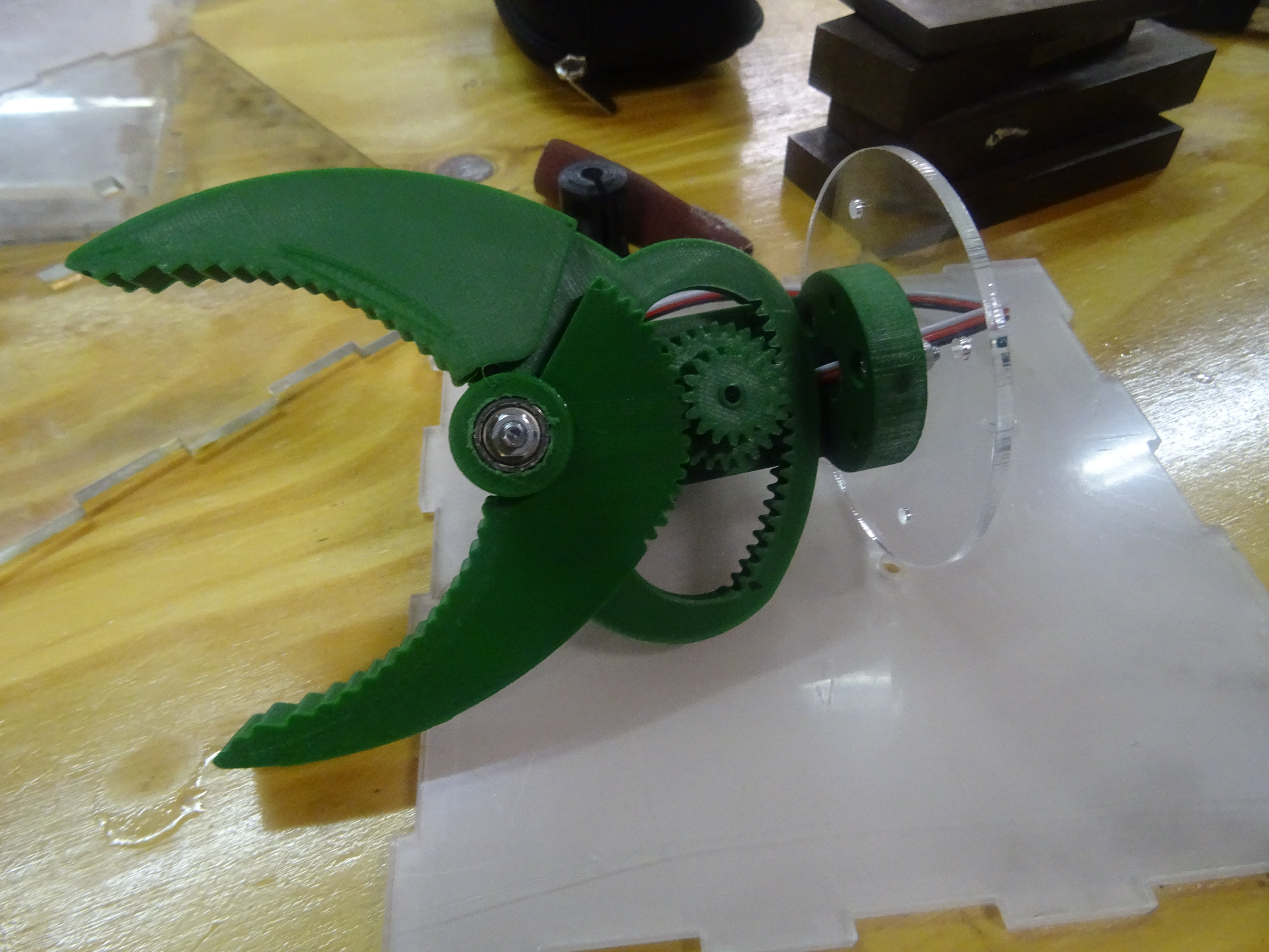
The servo rotation is converted to a gripping motion
Connections between the different parts
Another important part is to mechanically connect all the parts. For the gripper at the end of the arm, it is quite straightforward. The last segment of the arm will be connected using bolts and nuts. This requires some extra holes in the last segment.
For the case, it is a bit harder. Here the first segment will also be adapted with extra holes for bolts and nuts but it also required some glue for extra strength. The assembly of this concept is quite difficult because one must keep in mind that the wires are also passing this point and these should always be in tension. This gives another challenge discussed in the assembly part.
The connection between the arm and the box has to be very sturdy so glue and bolts are used