Electronics
Basics
The basics of the prosthesis consists of the use of an Arduino Uno that acts as the central processing unit. The arduino receives input from four sensors: two potentiometers, one joystick and an EMG sensor. It also gives output signals to three servo motors.
Servo motors
Three servo motors of the type Futaba S3003 were used in the prosthesis. Two are controlling the movements of the arm itself by rolling a wire on a spool, the other one controls the gripper.
The servo motors that are controlling the movement of the arm are hacked so that they are no longer restricted to only rotate 180 degrees, but so that they can turn indefinitely. This has the disadvantage of not being able to control the position anymore. To overcome this, at the end on the shaft, a potentiometer is placed to still be able to determine the position. The potentiometers that are used, are ten turn potentiometers, so the code has to prevent the axis from turning more than the potentiometer can handle.
The other servo motor is connected to the gripper, and can only rotate for 180°, this corresponds to the open and closed position of the gripper. This gripper is controlled by an EMG sensor, which means that the user is able to open and close the gripper by the means of tensioning of flexing a muscle.
Sensors
EMG Sensor
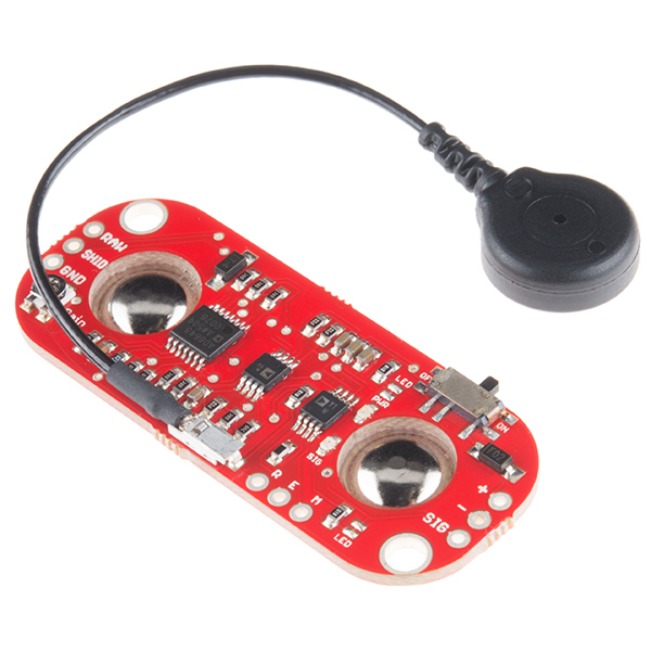
The Sparkfun Myoware EMG sensor is used
An EMG sensor is able to detect electrical activity of a muscle and converts it to a single voltage that the Arduino can use. This preprocessing of the raw data is done by a chip on the sensor itself, which amplifies, rectifies and integrates the measured signal. This decreases the load of the calculations for the Arduino a lot, and therefore making the overall system able to respond faster.
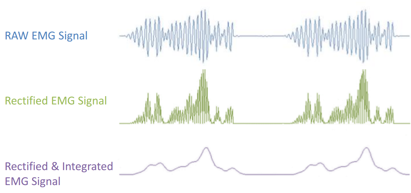
The Datasheet specifies that the output is a rectified and integrated signal
The sensor has three electrodes, two should be placed at the beginning and middle part of the muscle, while the third one acts as a reference and should be placed on another muscle or a bony piece of the body. For this project, the biceps was used, and the best results are obtained when placing the reference electrode near the side of the elbow.
The value eventually received by the Arduino is in the range 0-1023. High values are measured when contracting the muscle while lower ones are obtained in a relaxed position. As the wanted behaviour is the opening/closing of the gripper, a threshold value must be chosen where the gripper changes its position. Experimental tests found out that 800 is a good value.
Joystick
A joystick is used to control the motion of the arm itself, this makes it easy to control both the x- and y-direction at the same time. However, this was not the main reason to choose a joystick for the control.
A real prosthesis would be controlled only using EMG or other biometric sensors. As an EMG sensor costs around €50, buying three instead of one would consume a big part of the budget (€200). A joystick costs a lot less and is considered the best alternative.
The joystick consists of two potentiometers, one for the x-axis and one for the y-axis. Both values can be obtained at the same time, using different analog pins on the Arduino.
Potentiometers
At each spool axis, a potentiometer is placed in order to have some kind of feedback for the continuous rotation servo motors. They are also used as a protection by limiting the movement of the arm once a certain amount of turns is reached. Without this protection, the arm would be able to tangle itself by moving too much, as seen on the image below.
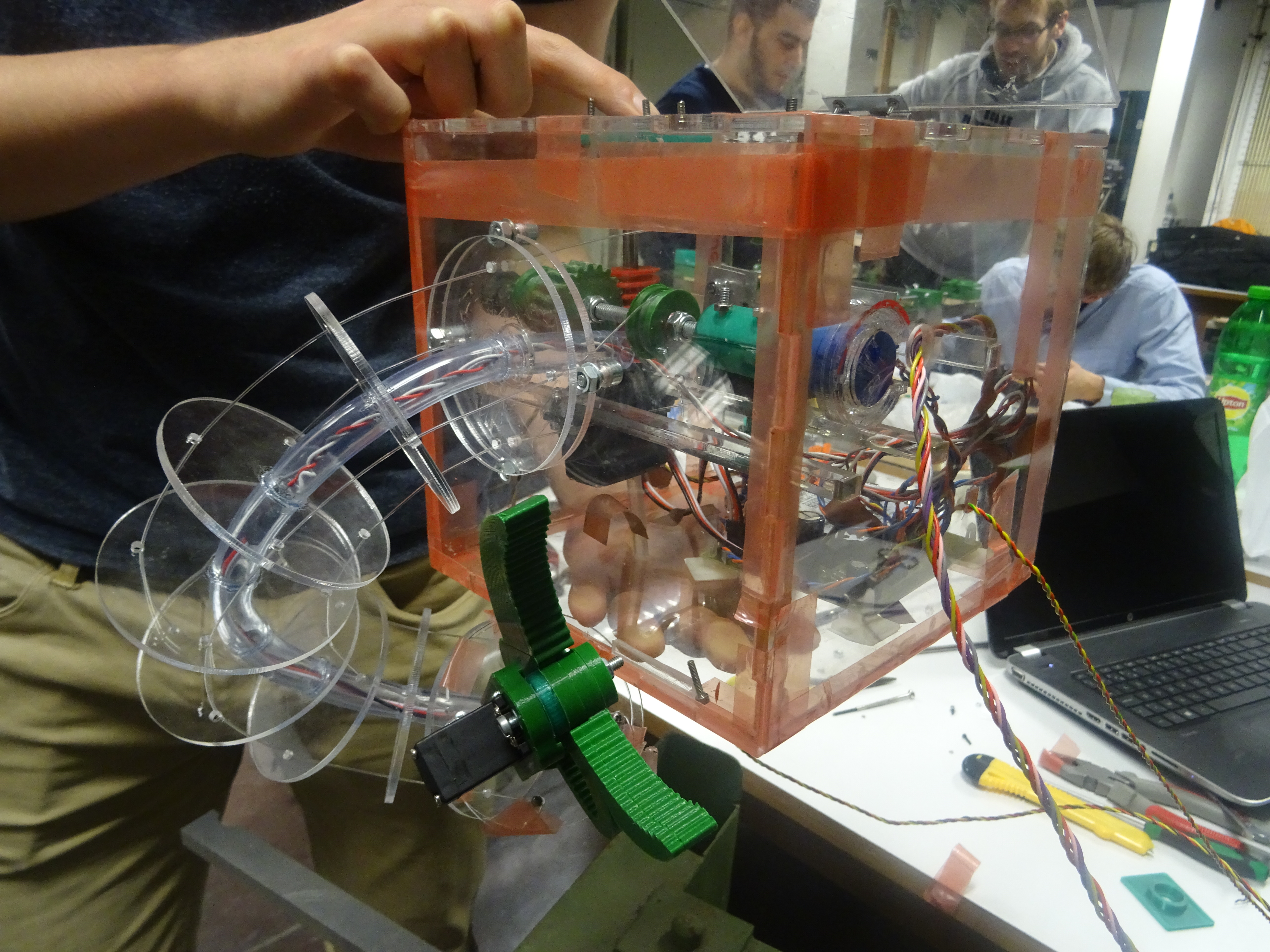
Without electronical limits, the arm can tangle itself, which could damage the system.
The potentiometers that are used, are ten turn potentiometers. That means that, if the arm is in relaxed position, the potentiometer should be in the middle of its range and can turn five times in each direction. This also impacts the design of the spool, as the maximum elongation and shortening of a wire is five times the circumference of the spool. Preferably, there should even be some margin left to address possible errors.
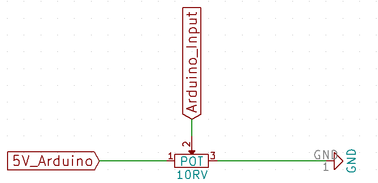
The implementation of the potentiometer
The potentiometers are fed with the 5V line of the Arduino, and pin 2 of the potentiometer is connected to an analog input.
PCB Design
All the electronics are put in a compact PCB design, this was done using the free program KiCad. The PCB can be divided into two main parts. The first big part is the buck converter, responsible of converting a 7.2V source (e.g. a Lithium battery) into a suitable voltage source (5-6V) for the servos. A buck converter is a switch mode power supply. The main advantage of a switching mode power supply over the classically used linear regulators is its high efficiency. With a linear regulator, the difference between the input and regulated voltages is dissipated as waste heat. This is not the case in a switching mode regulator. With this kind of regulators, a device switches on and off to maintain a constant average value of the output. This means that there still needs to be some element to smoothen the waveforms coming out of the buck converter in order to obtain a DC signal. In this case, there was opted for the use a coil of 100 µH. The output voltage of the buck converter can be regulated by changing the ratio of the resistance of the resistors in it’s feedback loop. The output of the buck converter is fixed to 6V by choosing the right ratio of these resistors. This voltage source of 6V will be the voltage that is provided to the servo motors. This voltage corresponds to voltage at which the servos provide maximum torque.
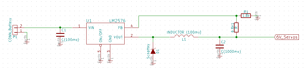
Used circuit for the conversion from 7.2V to 6V
The second large part of the PCB is the shield for the Arduino, responsible of connecting all the components at the right pins of the Arduino. The input signals for the Arduino are the voltages of the EMG sensor, the joystick and the potentiometers. These inputs are then processed by the Arduino, and based on these inputs, the output signals of the Arduino are sent. Three PWM ports are used as an output, this corresponds to one output port in order to control the speed of each of the three servos.
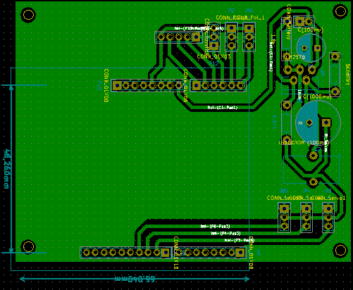
The PCB will hold all the different components
In the middle, the headers can be seen to plug the Arduino (represented by the teal rectangle) onto. The connection between the external components and the PCB is achieved by placing male headers on the PCB. On the top right side, the circuit of the buck converter can be seen. The routing for this component is critical. For a good operation, the length of the leads should be as short as possible. This is because the parasitic inductance of the printed circuit board traces can induce electromagnetic interferences, interfering with the normal functioning of this component. At the sides of the PCB, holes are drilled such that the PCB mounts can be installed on the PCB. The PCB is then fixed in the case with the help of these mounts.