Programming the PIC
In order to make the PIC do what you want it to do, it has to be programmed. First the assembler code needs to be written, then it needs to be compiled and uploaded to the PIC.
Below you will find the steps taken in our assembler code for making the Smartcard reader read the bank card number from a bank card. To understand what some of these steps mean in detail, previous sections of this website need to be read first.
Assembler

Documentation & Sources
Assembler Source Code
Internet
Assembler Code: list of operations in error-free conditions
-
I.Initialisation
-
-
1.All variables that are used in the program are declared and assigned addresses.
-
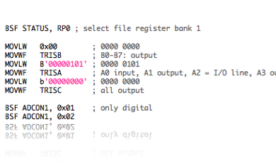
2.Ports A, B and C are configured as in- or output.
-
•A0: Card Inserted (switch contact of the card reader)
-
•A1: RST signal for the Smartcard
-
•A2: I/O port for the Smartcard
-
•A3: Signal to the door (open or closed)
-
•B0-B7: Data ports for LCD screen
-
•C0-C3: Not used
-
•C4: Register Select for LCD screen
-
•C5: Enable Signal for LCD screen
-
•C6-C7: For serial connection with computer
-
3.Initialise Serial Connection, baud rate set to 2400
-
4.Initialise LCD screen: 8 bit mode, 2 lines, cursor hidden, clear screen
-
5.Put welcome message on LCD screen
-
-
-
II.Card Session
-
The cardreader is now ready to receive a card and read its contents.
-
-
a.Begin Card session
-
-
1.Put “Please insert card” message in LCD screen
-
2.Start a new card session: wait for card to be inserted
-
3.When inserted, clear all variables and initialise parameters and ports
-
4.Check if the I/O line is set to High by card, or reject the card (wrong side error)
-
5.If the I/O line is High, send the Reset signal to the Smartcard
-
6.Write “In progress” to LCD Screen
-
-
b.Answer to Reset
-
-
1.Wait for the ATR to begin
-
2.Receive the ATR
-
3.ATR verification
-
-
c.Acquire Bank Card Number
-
-
1.Write progress bar on LCD screen
-
2.Select root DF
-
3.Select purse EF
-
4.Read purse file binary content
-
5.Extract Bank Card Number from the purse file content
-
-
d.Verification of Bank Card Number
-
-
1.Transmit Bank Card Number on serial port
-
2.Wait for access data from computer
-
3.Verify access data (contains user name and access allowed/denied info)
-
4.Allow or disallow the user to enter
-
•on allow: print welcome message on LCD screen, including the user’s name from the database, open the door for about 5 seconds and ask the user to remove card on LCD screen
-
•on denied: write “Access Denied, remove card” to LCD screen
-
-
e.End Card Session
-
-
1.Wait for Card removal
-
2.On card removal, go to §II (Card session)


Note: The above list of operations assumes that there are no errors in sending or receiving data from the card, as well as sending and receiving data from the serial connection. Also it contains no detail on how exactly the transfer of bytes from the card to the PIC is done and vice versa. For details on this, we refer to the .asm code file which is available at the top of this page. Some notions of assembler coding will be required to understand the code.