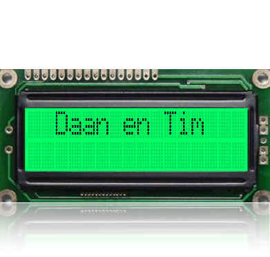
The LCD Screen
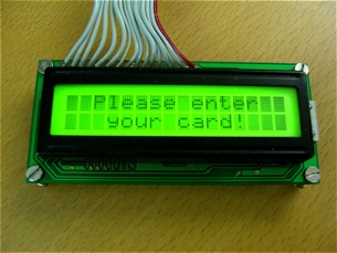
The LCD screen allows the user of the electronic accessing system to get feedback about what exactly is going on. More specifically, the screen will tell the user if the card is being read, rejected, or that access is granted or denied. If the user is allowed access, a welcome message containing the user’s name should appear on the screen.
LCD

Documentation & Sources
Datasheets
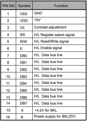
It is clear that on the PIC, 8 ports will need to be reserved for sending data to the LCD (pins 7 to 14), and 2 ports for controlling the data flow (pins 4 and 6). Pin 5 will be applied to the GND as we are not interested in reading data from the LCD screen (only writing to it).
Er moeten dus 8 data poorten (pin 7 t.e.m. 14) en 2 poorten voor de aansturing (pin 4 en 6) gereserveerd worden op de PIC. The ports used on the PIC will be port B (8 ports) for the data outputs, and ports C4 and C5 for the two control signals.
Pins 15 and 16 are for the backlight and are to be connected to the Voltage source (5V) and the GND respectively.
Pin 3 sets the contrast and needs to be set between 0 to 1 Volts.
Controlling the LCD screen is done using 16 pins, as is shown in the photograph below. The meaning of what the pins are for can be found in the table below.
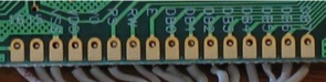


Note: the brand of our LCD screen was unknown, however, most LCD’s are used and controlled in a similar fashion, which allowed us to use datasheets of other LCD screens than our own.
Controlling the LCD screen is done using two modes which are defined by the control signal RS (Register Select). When RS is Low, the LCD will accept commands that alter its settings. This is needed for initialising the LCD. We can specify whether the LCD screen works in 8- or 4-bit mode, how many lines are visible on the screen (1 or 2), whether the cursor is visible and so on (more info on commands can be found in the datasheets). The manner in which instructions are being processed is as follows. The code for a specific command, consisting of 8 bits, is put

onto port B on the PIC. The LCD will wait for a downward slope of the control signal E (Enable). When this downward slope is detected, the LCD will accept the command on port B, and execute it. For every command, a negative pulse will have to be sent to the “Enable” port.
When the LCD is initialised, RS is put to High, which defines the second mode of operation. In this mode, characters can be sent to the LCD. The characters are sent one by one and written next to each other on the LCD screen. Only 16 characters will fit on one row. A “Next Line” command will need to be sent to begin writing on the second line. A “Clear Screen” command will need to be sent in order to write a new message to the screen. The sending of characters is done identically to the sending of commands, the only difference is that the RS port is set to High instead of Low.