The SmartCard
Understanding, controlling and reading the SmartCard is without a doubt the most complicated and time consuming part of this project. The main reason for this can be found in the lack of information. Also the timing of bits in smartcards is extremely difficult and can differ from smartcard to smartcard. To remain comprehensive to (most) visitors of this website, we will try to give a simplified overview of the workings of the Smartcard chip. It has to be noted that to fully understand and make the communication of the Smartcards work, it is mandatory to have thoroughly studied the norms which can be downloaded on this page.
De SmartCard

Documentation & Sources
Norms
-
• ISO/IEC 7816-1 t.e.m. 4
Physical Characteristics
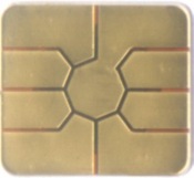
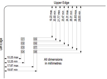
A first step in controlling an ICC (Integrated Card Circuit) is to identify the contacts that can be found on the chip card and to connect them to their appropriate ports.
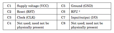
On the ICC, 8 contacts can be found, of which C4 and C8 are not used in general. The ICC is fed with a 4.6 to 5.4 Voltage source. Contacts C2 and C7 are being connected with ports A2 and A1 of the PIC respectively. These ports will manage the control of the Smartcard. Port C3 is the CLK (Clock) signal, which needs to be between 1 and 5 Mhz according to the norms.
Contact C6 is used for programming the smartcard and is not used in the scope of this project.
Activating the Smartcard
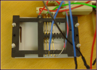
Once the card is correctly connected, it has to be activated. The card is inserted into the card reader. A mechanical contact (switch) will allow us to detect whether a card has been inserted into the card reader.
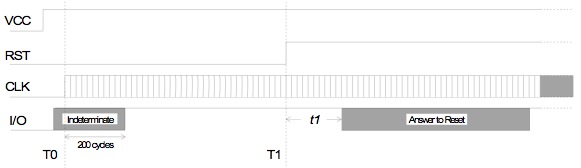
When the card is inserted correctly, the voltage source will be applied to the ICC. Some time after applying the voltage, the ICC shall set its I/O (input-output) port to High.
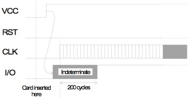
This is an indication of whether or not the ICC is correctly connected and allows us to detect if the card is inserted correctly or needs to be flipped (wrong insertion).
Resetting the SmartCard
When the I/O port has been activated, the ICC will wait for a RST (Reset) signal. The Terminal (in our case the PIC) will need to supply this signal by setting its RST port to High.
Character Frame
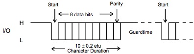
Following the RST signal, after a time (T1), the card will send an answer. This answer is called the Answer to Reset (ATR), and contains a load of information about the workins of the card and how it has to be operated. The ATR is sent to the Terminal one bit at a time, over the I/O line. The figure below shows how one character is transmitted over the I/O line.
One can see that to send 1 character, 10 etu (elementary time units) are needed. An elementary time unit is the time the ICC will allow for the Terminal to read one bit of the I/O line. This timing is an essential part of the correct interpretation of characters by the Terminal. More detailed information about how an etu is defined can be found in the norms. The sending of one character begins with the ICC setting the I/O line to Low for one etu. Following this start bit, the 8 data bits that form the byte that the ICC wants to transmit are sequentially put onto the I/O line. After the data bits one last bit, called the Parity bit is transfered. The parity bit is used in a way to check whether the character sent by the ICC is correctly interpreted by the Terminal. Its value shall always be set so that the amount of ones in the character frame (including the parity bit itself) is even. If this is not the case, a so called Parity Error has occured and the Terminal will need to take control of the I/O line to let the ICC know there was an error. The ICC will then try to resend the faulty character. More information about this error handling can be found in the norms. When a character has been sent correctly, the ICC will leave the I/O line High for some time (the Guard Time) before sending the next character.
Answer to Reset
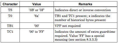
As noted, resetting the card will result in the Answer to Reset (ATR). Now that we know how bytes are being transferred and how to correctly read them with the Terminal (PIC), one can interpret the ATR in order to assure correct control of the ICC. Depending on the ICC, we need to use either communication protocol T=0 or protocol T=1. Because of our limited time for this project, only the T=0 protocol has been implemented. This protocol is used for most (if not all) bank cards. The ATR for a T=0 card is as follows.
The first byte (TS) that is being sent in the ATR has two purposes. Its first purpose is to synchronize the terminal and the ICC (more details can be found in the norms), the second purpose is that it allows the Terminal to see whether the Direct or Indirect convention is being used by the ICC. Direct convention means that the l.s.b. (least significant bit) of the byte is being sent first over the I/O line. The indirect convention will send the m.s.b. (most significant bit) first. For most cards, the direct convention is used, in which case the TS byte is set to ‘3B’.
The second byte (T0) will allow the Terminal to know the protocol that is being used by the ICC. When the msb of T0 is High, protocol T=1 is used and the card will be rejected (because T=1 is not supported by the Terminal). The following 3 bits will tell whether the characters TB1, TC1 and TD1 are present in the ATR. The 4 lsb compose the number of historical characters present in the Smartcard. These historical characters are part of the ATR and are sent at the very end. They do not contain any useful information for this project. More information about the historical characters can be found in the norms.
If TB1 is present in the ATR (depending on the value of T0), its value will need to be ‘00’ for protocal T=0.
If TC1 is present in the ATR (depending on the value of T0), it will determine how much guard time is being used in between the sending of two characters. If its value is different from its standard value, the Terminal will need to apply the correct guard time immediately for all further communication (more information in the norms).
The historical bytes (max 15) are being sent lastly. Their value is of no importance, yet they do need to be read in order to avoid confusion about which device (ICC or Terminal) has control over the I/O line (i.e. who is the sender and who is the receiver). The ICC and the Terminal shall know at any given time who is sending and who is receiving.
More detailed information about the ATR can be found in chapter 8 of the ISO/IEC 7816-1 norm.
Reading the Smartcard
Once the ATR has been read by the card reader and approved (i.e. all tests on the ATR values have been passed), the ICC will put itself in receive mode and shall accept commands sent by the terminal. This is the hardest part of the project, simply because nearly no information about sending commands to a smartcard can be found. The reason for this lack of information is that the commands are not identical for every card and every country. In what follows, we will try to explain how we were able to extract the necessary information from the card.
The goal is to find a way to get information from the card that is unique for the card that’s being used. For this project, two different approaches to getting such a number were tested.
A first attempt was to use the “READ RECORD” command. The answer to such a command should always contain the Primary Account Number (PAN) of the card owner. This attempt was unsuccessful because the INS byte (more info on that later) was not recognized by the ICC.
In our second attempt, the so called “purse file” is being read on the ICC. As the name suggests, the purse file contains information about the card such as how much money is left on the card (Proton in Belgium), the currency used (euro’s), but also other information like the expiration date of the card and so on. More importantly, it also contains the bank card number consisting of 16 numbers which are unique for the card used. We will try to extract this number from the bank card using the “READ BINARY” command, which is not an easy task, because information about the way this should be done is scarce.
First we will explain the ways of sending commands to the Smartcard.
Sending commands to the Smartcard
A typical command consists out of an amount of bytes that are being sent by the terminal to the ICC. The way of sending these bytes happens in the same way the ATR was sent to the terminal, using a Character Frame. Note that all settings specified by the ATR should be applied, for example the etu can be set to something different that the initial etu used in the ATR: we now need to use the wetu (work elementary time unit, more info in the norms). The bytes are being sent by the terminal, so it is also the terminal that needs to generate and send the parity bits for each character. After every byte, the ICC checks the parity and sends an error signal when the byte is wrongly interpreted. The checking of the error signal and the resending of the erroneous byte isn’t discussed on this webpage, more info can be found in the norms. By now it should be clear that the communication between ICC and Terminal requires a lot of changes in the direction of the data stream (terminal to ICC and vice versa), this is also one of the reasons why the communication is a complex thing to accomplish.
The amount of bytes in a command and their meaning depend on which command is being used. A set of command bytes that form a command are called an Application Protocal Data Unit (APDU). Depending on which command is being issued, an APDU will consist of one or multiple C-APDU and R-APDU’s. A C-APDU (command APDU) is sent by the terminal to the ICC and a R-APDU (response APDU) is sent by the ICC to the terminal. Different kinds of commands exist, each with their own specific APDU’s. 4 types of commands exist (case 1 to case 4), depending on how many times the data stream changes course (terminal to ICC or ICC to terminal). A very brief and insufficiently clear overview of the different commands can be found in the norms.
To understand how to get the bank card number from the card, one needs to know how the data structure inside the ICC is built. As usual, little information about this could be found.
The data structure can be compared to a UNIX system, where one has a root directory in which files and directories reside. Every directory can contain other directories and files. In the norms, these files are called Elementary Files (EF), and the directories are called Data Files (DF). DF’s as well as EF’s each have their own address, consisting of two bytes. For example, the root DF has the address 3F 00, and the purse EF has the address 29 01. The purse EF resides directly in the root DF and its complete address would be 3F00:2901. To open the purse EF, one needs to browse to this EF using the “SELECT FILE” command. First you need to select the root DF (3F00) and then you can select the purse EF (2901). Once the purse file has been selected, its contents can be read using the “READ BINARY” command.
A typical C-APDU would have the following general structure.
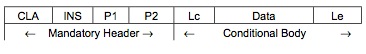
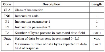
CLA is the Class byte. It depends on the ICC type and the application used. The INS (instruction) byte determines which instruction/command we want to execute. P1 and P2 are parameter bytes that can be used to supply extra information that is needed for some commands. The value of Lc lets the ICC know how many Data bytes will follow. The value of Le lets the ICC know how many Data bytes are being expected in the ICC’s R-APDU.
For our project 2 commands are being used. Letting these commands work was essentially done using trial and error methods (because of the lack of decent information). Especially finding out what the class byte was for Belgian cards was a great difficulty.
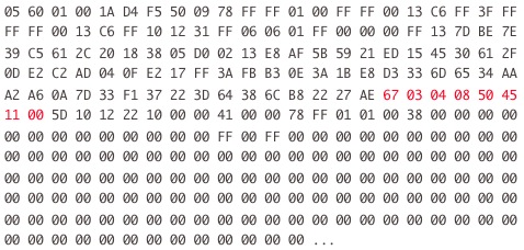
The first 255 bytes of the purse EF are shown below:
The bank card number can be identified as being byte 105 to 112. We checked this position with different cards and we were happy to see that this was always the case.
The bytes are being read and immediately transmitted to the PIC which transmits them to the PC. The problem with this is that the ICC sends the bytes a lot faster than the serial port can manage. We found a way around this problem by reading the purse EF 8 times in a row, selecting a different byte from the bank card each time (see the assembler code for more info on how this is done).
When all bytes of the bank card number are sent to the PC, the PC will check these bytes with a database and let the PIC know whether or not to open the access door and display a welcome message on the LCD (we refer to the respective sections for these operations).
Reading the purse file
As was said before, 3 commands need to be executed: selecting the root DF, selecting the purse EF and reading the purse EF.
Selecting the root DF
-
• C-APDU: BC A4 00 00 02
-
The Class byte is BC, depending on the ICC. Finding the Class byte for Belgian bank cards was not easy, but apparently it is ‘BC’. The instruction byte ‘A4’ lets the ICC know that we want to execute the “SELECT FILE” command. Parameter bytes P1 and P2 are not necessary for this command and are being put to value ‘00’. Lc and Data are not present for an A4 instruction. Le is set to ‘02’ because the root DF address consists of two bytes (3F 00).
-
• R-APDU: A4
-
The C-APDU results in a R-APDU containing a procedure byte. For the C-APDU we sent, the procedure byte will be equal to the INS byte, i.e. ‘A4’, which basically means that the first C-APDU was correctly interpreted by the ICC.
-
• C-APDU: 3F 00
-
The terminal then transmits the two data bytes that consist of the root DF’s address (3F 00).
-
• R-APDU: 90 00
-
When the command is executed, the ICC will answer with two status bytes. These status bytes allow us to see whether the command was executed or whether an error occured. If an error occured, the value of the status bytes will give an indication of the kind of error that has happened. When the command has been executed successfully, the value of the status bytes will be 90 00.
Selecting the purse EF
-
• C-APDU: BC A4 00 00 02
-
Analogue to previous command.
-
• R-APDU: A4
-
Analogue to previous command.
-
• C-APDU: 29 01
-
In this case the data bytes contain the purse file’s address.
-
• R-APDU: 90 00
-
Successfully completing the command results in status bytes 90 00.
Reading the purse EF
-
• C-APDU: BC B0 00 00 FF
-
The Class byte (BC) remains the same. The INS byte is now ‘B0’, which stands for the “READ BINARY” command. Paramters P1 and P2 are set to ‘00’ because they are not needed for the ‘B0’ instruction. Lc and Data bytes are not present. The last byte, Le, determines how many bytes we want to read fromt he purse EF. In our application, we choose to read 255 bytes so we set Le to ‘FF’.
-
• R-APDU: B0 [DATA] 90 00
-
The procedure byte contains again a repetition of the INS byte. Immediately after the procedure byte, the contents of the purse EF are transmitted (at least the first 255 bytes of it, as specified in the C-APDU). Successfully completing the command results in status bytes 90 00.
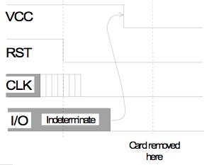
The goal in what concerns the Smartcard is now complete. The unique bank card number has been read correctly. The only thing that remains is to deactivate the card in an appropriate manner. This is done by setting the Reset signal of the ICC to Low. This will result in the I/O line being put to Low by the ICC. Only then can the Voltage source be disconnected by pulling the card from the card reader.
In conclusion
We hope that with this page we can supply a comprehensive introduction to the understanding and using of Smartcards. The reason that this page is written more or less in the form of a manual is that we didn’t find anything like this on the internet and therefore we hope that students who have a future project with Smartcards will get through the start-up phase of their projects a lot faster, because the understanding of Smartcard protocols takes an enormous amount of time without decent information sources.
Furthermore it has to be noted that in this webpage, many aspects of the Smartcard’s workings are left out (one can write books about smartcards). The norms should supply sufficient extra information on getting your own Smartcard reader to work.