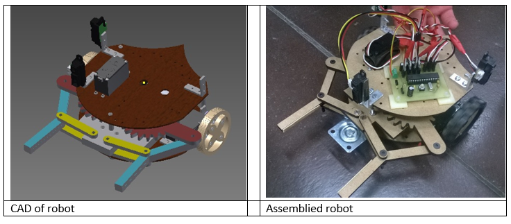
The Robot
Wheels
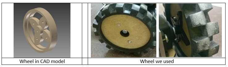
Since in the maze high speeds are not required and robot should be agile, we decided for two driving wheels. A third support point is needed as we are not planning on stabilizing the robot on only two wheels. In CAD model we designed fancy wheels which should be 3D printed. Unfortunately the printer was quite occupied at Fablab and we thus decided to cut the wheels out of rests of MDF plates. This method was faster and cheaper. Later on, some Lego Mindstorm tyres that suited our wheels were found at the lab.
DC motor
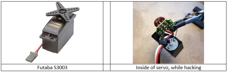
Some calculations were made in the early days of the project but in the end we just tested the servo motors that were available in the lab. Fortunately they were powerful enough and could handle the load of our robot. The servos were of model FUTABA S3003. Two of them are used for traction and have been hacked, one is used for the gripper for which a 180 degrees rotation is sufficient. Advantage of these motors is that they are cheap and already have electronics and gear inside. Moreover Arduino code already exist under the library Servo in order to control them.
Gripper
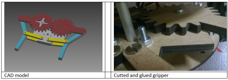
A common gripper used in robotics was chosen. The main advantage of it is its simplicity in terms of working principle and number of parts . The dimensions of the mechanism were finally adapted in order to implement is in our design. This process took more time than expected. Since it is 3D construction, we cut it from MDF. At the time when we wanted to cut it, lasercutter was not working properly and we couldn’t use 5 mm MDF. Instead of that we cut it two times from 3 mm thickness and glued two layers together. It worked!
Platform
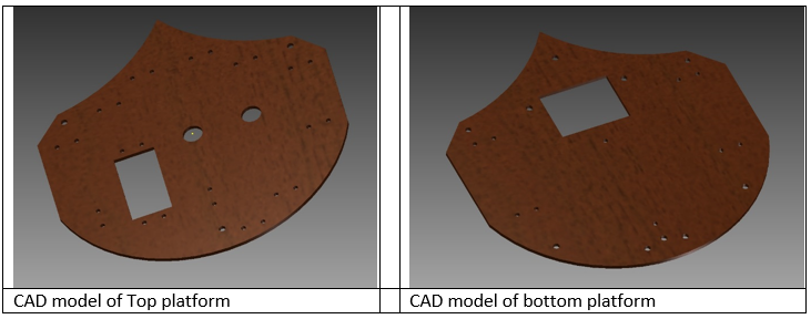
We decided for two floors, so robot occupies less space in the maze. On first floor we put heavy things like batteries and gripper. On top floor, there is electronics and sensors. We made two big holes for the cables and a lot small holes for attaching everything else. On top platform we have more holes than needed, so we can move our IR sensor on different positions to see where is optimal.
Screws and connecting elements
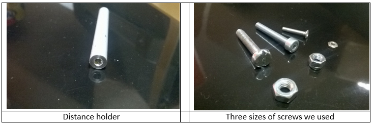
Three distance holders with thread keep both platforms on the certain distance. L profiles with holes hold sensors and DC motors on their positions. These components are from aluminum and were made in the workshop near the lab. Also all screws and nuts needed were taken from there.
Photoresistor box
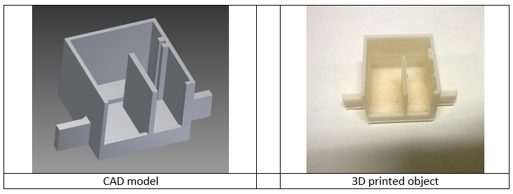
In order to detect a white line, a sensor incorporating a white led and a photoresistor are made. For good functioning of the sensor, the photoresistor, which detects white light, should be shielded as mush as possible from the led in order to avoid direct incidence of light from the led. Indeed, the desired light beams for measurements should be the ones reflected by the floor surface. To do so, box for the sensor was modelled using CAD software and 3D printed using a cheap printer. Note that some post processing was necessary to cover or adjust defects from 3D printing. To become a satisfying end result, the box was modelled by putting extra mass at the side the 3D printer would fail. This extra mass was eventually removed by technicians using a frace.
Final assembly