.jpg)
Electronics
Receiving network
Guiding through demodulation
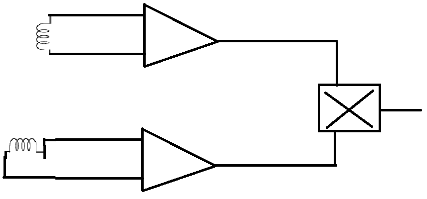
The idea to detect if the robot is left or right of the electrical wire is by computing the product of the measured magnetic field using a reference and measuring coil. This technique used is called product detection, an application of demodulation. The idea is illustrated in following figure:
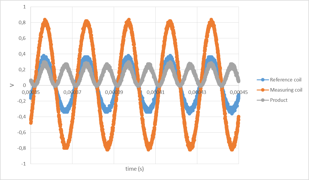
Testing the reference and measurement coils, following results were obtained while being right of the wire:
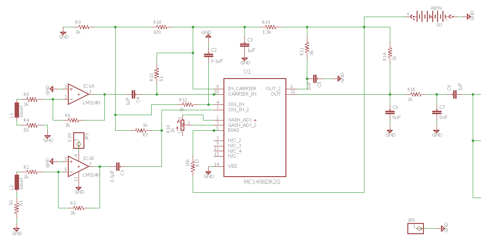
Real-life design of the receiver
The entrance is at the inductors L1 and L2 which pick up the wire signal (they are filtered at 50kHz with a capacitor in parallel which is not mentioned because they are already soldered on the inductors so they didn't take any space on the PCB). The picked-up signal gets a gain at IC1A and IC1B so the incoming signals at the demodulator chip are approximately 300mV RMS (the exact value of the gain still have to be determined, since that depends on the measured amplitude). Notice that there is also a ground-connection with JP5, this is to connect the ground of the PCB to that of the Arduino, to avoid having a floating ground.
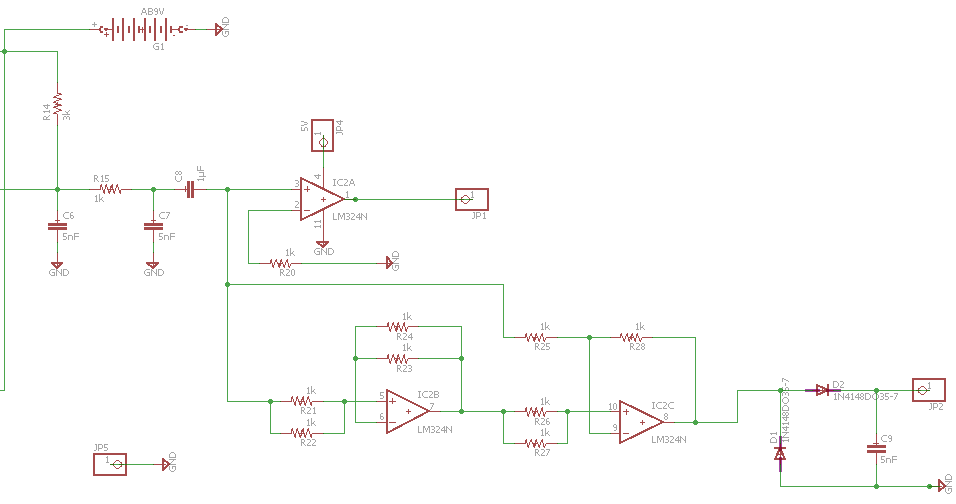
After the demodulation the picked-up signal will be transformed into half sine waves, who are eather completely positive (robot is right of the wire) or completely negative (robot is left of the wire). This signal is split into two. One of them goes to a comparator, who checks if the half-sine wave is positive or negative.
This done to keep the full range of 0-5V (left and right) for accuracy to steer the robot. A sommator circuit could habe been used to shift the outcomming signal of the demodulator (because Arduino can’t handle negative voltages), but that would have resulted in a lower range to steer (approximately from 0-2.5V for negative (left) steering and from 2.5V-5V for positive (right) steering, which is twice as low).
So now the other end of the demodulator is coupled to a absolute value circuit (to obtain positive values in order to avoid burning the Arduino). For this reason a comparator was used, because the comparator sends to the Arduino whether the incoming wave is negative (left) or positive (right).
After the absolute value circuit, a AC-DC-converter circuit was placed, in order for the Arduino to be able to handle the outcomming in an optimised way.
Unfortunately this didn't worked. We searched for some possible solutions and came out with several possible solutions. C1 and C4 should be removed, because they influence the frequency on which the detection coils are filtered, because capacities can be added when placed in parralel. So because of C1 and C4 the frequency is no longer tuned on 50kHz.
Also, at the end of the demodulator C6 and C7 are used as low pass filter and together with C8 they filter out the mean of the output signal of the product detection. Unfortunately the mean is not what we wanted. This filtering is only necessary for audio signals (AM radio demodulation/product detection). So by also removing especially capacitor C8 (C6 and C7 don't need to be removed they also have use in our system) the problem will likely be solved.
So as conclusion we can say that we trusted too much on the datasheet of the demodulator, because we couldn't find any other information that was applicable to our case. Later on we suffered from this consequence, so a new scheme had to be made.