.jpg)
Electronics
Introduction
To be able to detect and follow an electrical wire, a current with a certain frequency will have to be generated and measured. In order to do so two electronic systems were constructed: a signal generator and a receiving network. Furthermore, a SHARP infrared sensor was used in order to detect objects on the path.
AC-generator
The current flowing through the wire will have a frequency of 50 kHz, that way interferences will be minimal. A signal generator, generating a 50 kHz signal, was thus designed and tested. Based on following circuit a 50 kHz sine wave was created:
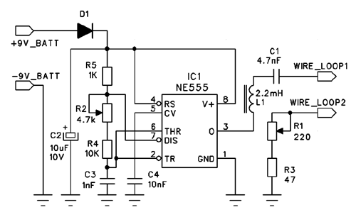
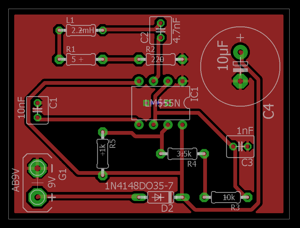
Out of this circuit the following PCB was made:

Receiving network
Principle of detection
First the idea was to use the demodulation principle (see Guiding through demodulation) , but since problems occured, changes were applied to the electrical scheme. This problems were mainly due to a shortage of information available about product detection (the used demodulation technique) for tracking purposes (mainly radio applications were found). This resulted in an unwanted signal at the end of the circuit.
So the used principle was good, but badly executed. A possible solution was suggested afterwards, but this is further explained in the demodulation section, where also extra info can be found about product detection.
As already mentioned, it would probably have been possible to solve the problem, but due to a shortage of time, a whole new design was made (which indeed took less time than remaining focussed on the product detection) that consisted out of well known components (which was not the case with the demodulator). So a scheme was developed that creates an RMS-value out of the incoming sine waves produced by the left and right detection coils. Afterwards this RMS value was amplified to obtain a larger detection range.
Real-life design of the receiver
The entrance is at the inductors L1 and L2, which pick up the wire signal (they are filtered at 50kHz with a capacitor in parallel which is not mentioned because they are already soldered on the coils so they didn't take any space on the PCB). The picked-up signals are transformed to a RMS value with a specific gain at IC2A and IC2B. After this the amplitude of the signal is not yet large enough so they are amplified at IC2C and IC2D by an non-inverted amplifier. This was done in order to avoid a voltage regulator, which would be necessary with an inverting amplifier. This decision reduces the size of the pcb. Since the signal that comes out of IC2C and IC2D is not 100% flat, it is rectified by a peak detector with a capacitor of 5nF, which discharges fast enough in order to detect changes.
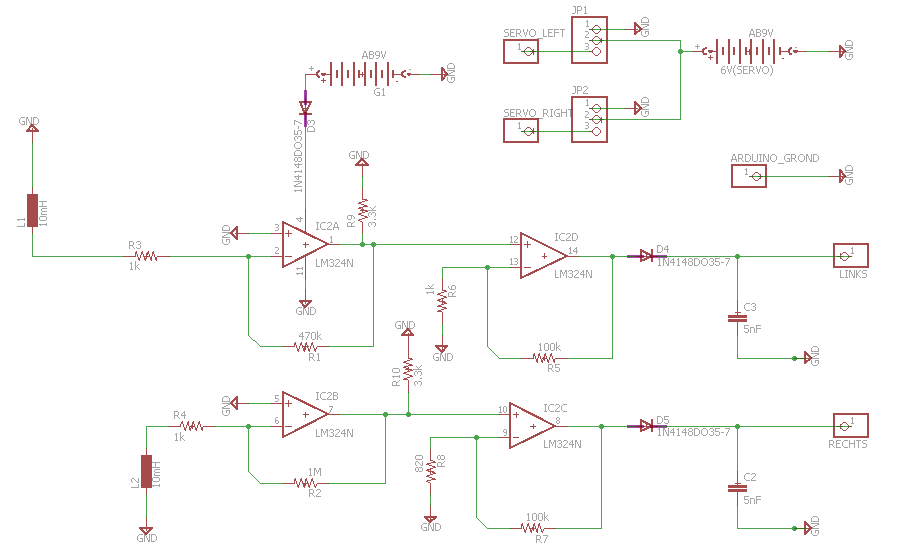
The signals at the end (so 'LINKS' and 'RECHTS') are then send to the microcontroller for processing (Arduino). The microcontroller is also connected with 'SERVO_RIGHT' and 'SERVO_LEFT' who give the signal that respectively controls the motion of the right and left servo. At the pin 'ARDUINO_GROND' the grounds of all used electronics are coupled with the ground of the Arduino so no floating grounds are created.
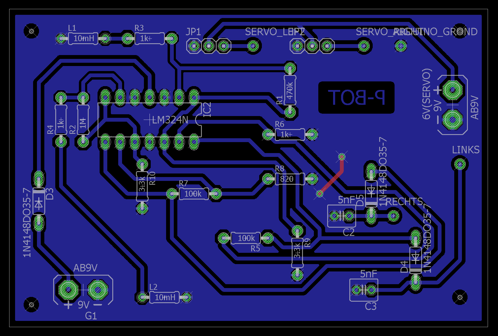
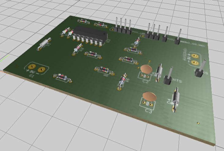
Out of this circuit the following PCB was made:
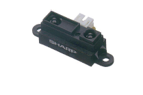
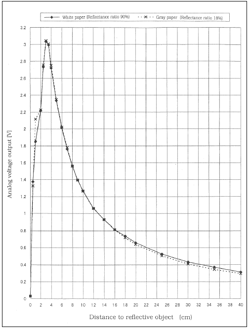
Distance Sensor
To make sure the robot does not take any damage, a collision-detection system has been implemented. Using a certain distance as treshold, allows the robot to stop in case of an object in his path. In order to do so a SHARP IR-sensor is used. Its characteristic was taken into account while implementing the code.