Motor
An appropriate motor had to be choosen to operate the catapult. It should have a relatively high speed and high torque. This was a bit of a problem because usually speed and torque are inversely proportional.
Using a catapult simulator online, we estimated the initial velocity required to throw the ball at a distance of at least 50 cm. Thanks to the results obtained by the simulator and the mass and inertia of the catapult estimated with SolidWorks, the required torque for the motor was calculated.
The first option was to use a hobby servo motor. The torque was good enough but the speed did not meet our requirements and thus the ball was not thrown more than a few centimeters away. The relatively low speed of servo motors is due to the internal gears integrated in the motor.
The second option was to use stepper motors. Stepper motors have inherently more torque than regular DC motors because of the way they operate. And since no gears were required to increase the torque, their speed was higher than for the servo motor.
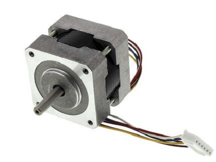
Since stepper motors are open loop system, it is always better to overdimension them for the required application. The following motor was chosen:
 |
|
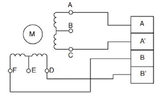
The motor is a 6 wires unipolar stepper. However, for this project a bipolar motor is needed. A simple way to transform a unipolar stepper into a bipolar stepper is to ignore the middle wire coming out of the coils.
The wires of pin B and E are neglected and the motor can now be used as a 4 wire bipolar stepper motor.
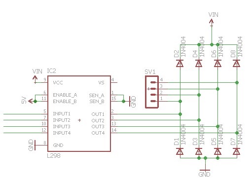
Since the Arduino can not deliver enough current to drive the motor directly, a dual H-bridged IC was used, in this case the L298 from STMicroelectronics. The L298 is an integrated monolithic circuit in a 15-lead Multiwatt and PowerSO20 packages. It is a high voltage, high current dual full-bridge driver designed to accept standard TTL logic levels and drive inductive loads such as relays, solenoids, DC and stepper motors. The Multiwatt package was used and connected according to the following schematic: