Schematic & PCB
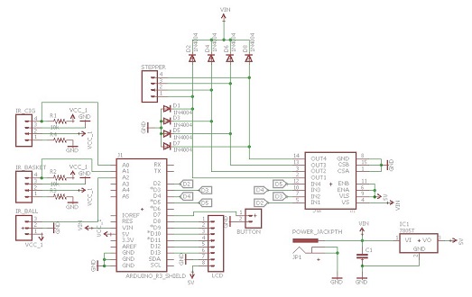
After choosing and testing all the components, we started the design of the PCB. The first step was to put all the components and connect them on the schematic in EagleCAD software. The schematic and the PCB are presented below:
 |
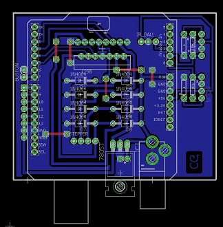 |
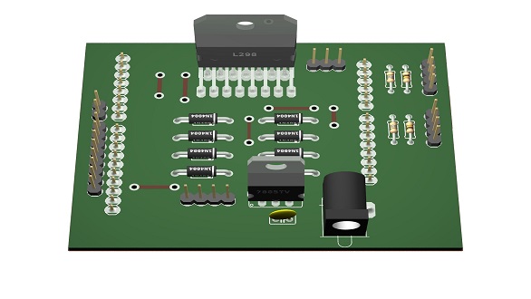
The PCB is an Arduino shield that has all the connections and components required. The electronics are powered by an AC to DC adaptor which makes the bridge between the regular power plug and the power jack on the PCB. This powers both the Arduino and the electronics. After finishing the layout and connections, the PCB was rendered to have a better idea of the final output. Eagle3D and POV-RAY were used and the final PCB rendering can be seen below: