Problems during the construction of the robot
A list of the problems which caused the robot to be unfinished before the original deadline (december)
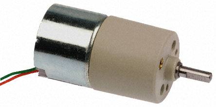
Motors
A first problem that occured, was that the motors were of very bad quality.
Wheel
The shaft diameter of the wheels are quite big. A 3D printed shaft needed to be inserted in this gap so there could be a connection between the motor and the wheels.
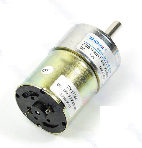
New motors
The new ordered motor for the wheels
Sponge mechanism
Since the motor was no longer available to make the sponge turn, the sponge could be in a rigid position.
Water tank
The water tank needed to be watertight. But this is more difficult to realise than first thought.
Brushless motor
The control needed for the brushless motor is difficult. It took a long time to find a correct way of programming it.
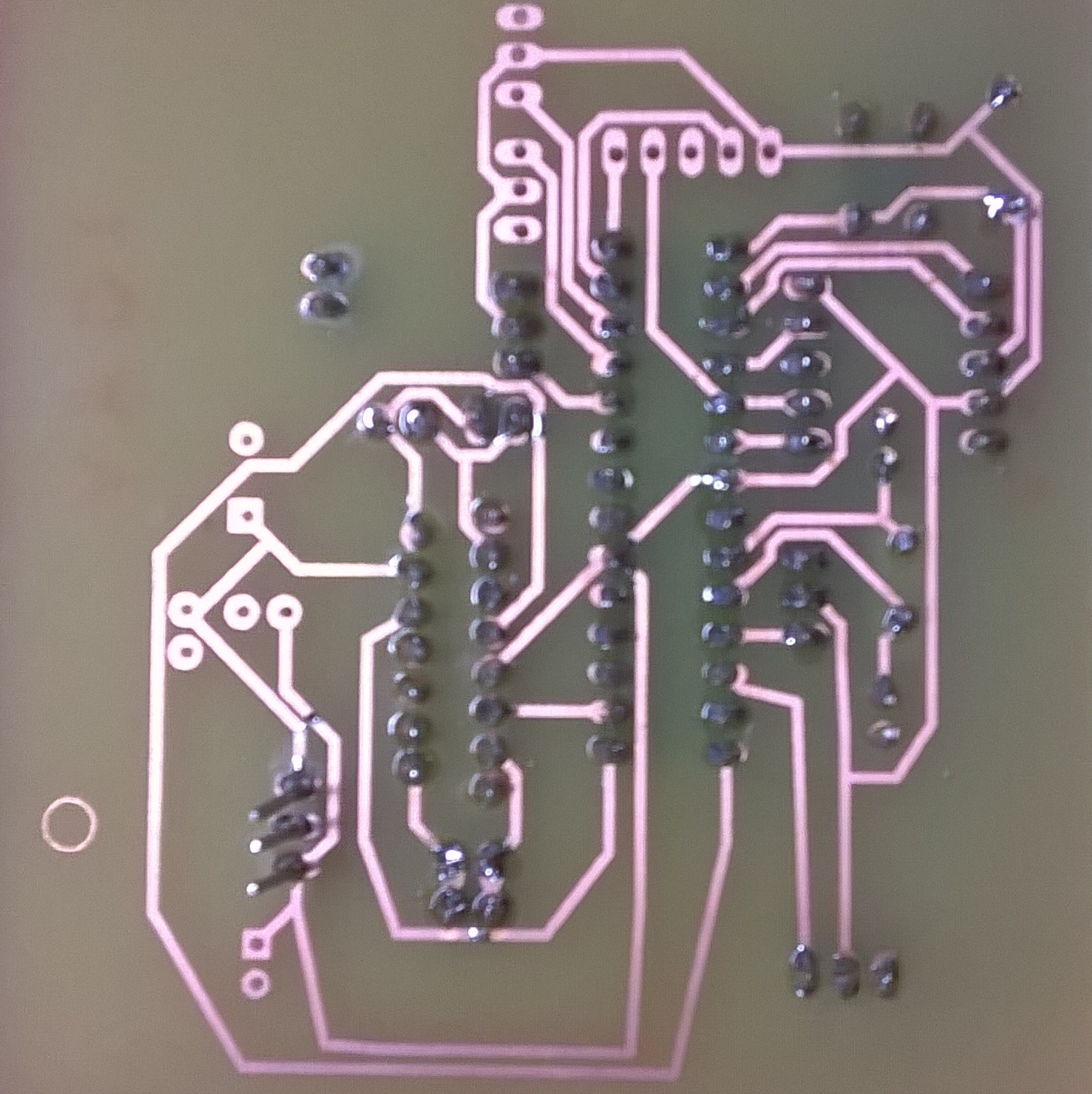
PCB
The wrong PCB without ground connections
Problem with the motors
The problem with the motor was that the axis didn't turn. This was due to the fact, that the gearbox blocked because of a shaft that was too long. This had to be solved by cutting the shaft, but the problem still occured sometimes.
Problem with the wheels
The 3D printed shaft fitted in the holes of the wheels but to attach them to the motors was a bit more difficult. After a lot of trying, we decided to glue these wheels to the motor. But since the mechanism of the motor wasn't very good, the gearbox got stuck and the wheel needed to be removed. So the shaft of the motor had to be cut and we lost a motor. We decided there would be no longer be a sponge.
New motors
Since the original motors were not really usable for the driving of the robot, new motors were ordered. These motors should have a slightly larger torque so that it could overcome the friction. Sadly the previous motors broke near the end and these motors could only be ordered after that this website was made.
Problem with the sponge
The sponge was placed in a fixed position so it could wipe the table clean. Only there was one problem: the sponge caused for a large amount of friction, which the robot couldn't pull. This was probably due to the original motors not having enough torque (the torque was considerably reduced due to the modifications made to the gearbox). This could be resolved by putting a pin at the back of the robot wich could give more support and less friction. This problem could also be solved by the new motors wich have a higher torque to pull the robot.
Problem with the watertank
The watertank was first glued together, but this didn't make it watertight. After applying silicone to all the crevices, it still wasn't completely sealed. So to make it definitely watertight, tape was applied and this did the trick. Unfortunately, the tape was quite thick, so this made the watertank no longer fit in the drawn hole. This had as a consequence that the connecting rod mechanism no longer worked. Due to lack of time, this couldn't be solved.
Problem with the brushless motor
The control unit (ESC) of the brushless motor was difficult to program, because somehow it wasn't possible to just give it one speed. To make the motor turn, an increase in speed had to be set and then it would turn at these different speeds. This took a while to figure out, but in the end, the motor was able to turn and the robot was able to suck screws and bolts (there weren't any crumbs available at that time in the lab).
Problem with the PCB board
For the first PCB that we designed, there was a misunderstanding with the eagle program. We tought that the bottom plate of the PCB would be assigned as ground automaticle and this led to a PCB board that didn't have any ground connections. Because of this we had to entirely redisign the PCB layout which led to a considerable loss of time.
When the new PCb was made, all the components were attached and everything seemed to worl. At least, almost everything. The only problem we had, was that the sensors were not read. We check the board for errors, but none were found. The sensors were not broken because they returned a value and even the pin of the microcontroller received the right value. By looking on the internet, there were some suggestions why it couldn't work, but none of the proposals seemed to work.
The only solution possible was placing the microcontroller back on the Arduino because there the sensors could be read, but the motors couldn't be controlled (because they needed 12V). So we connected a lot of wires from the Arduino board to our PCB so the motors could still be controlled. But this was not a pretty sight, but at least this worked.
After several tests, we saw that the wheels and sensors would work together, but then (probably because of all the wires) there was a short-circuit, which caused the controller to break. So a new controller was needed. This happened on the last official working day, so to continue working on this would be difficult.
Computer Aided Design Software
To build this project, we had to be able to design our robot on the computer. The aim of that is to know the exact dimensions of our pieces and notice before starting the construction that things would go wrong. The program we used was INVENTOR.
FabLab
When the design on computer was done, we had to build the robot. Few years ago, the robots could be made thanks to different techniques : turning, milling, drilling. Today, the technology evolved and we used for this project laser cutting to cut our plates of plexi and 3D printing for complex pieces. The machinery was available for us at the FabLab
Eagle
The PCB is an important part of the project. It enables to connect the microcontroller with ll the different parts of the project. The creation of it requires to be precise on the band width and the place of everything. To do it, we used a program, which gather a lot of electrical components to build those boards, called Eagle