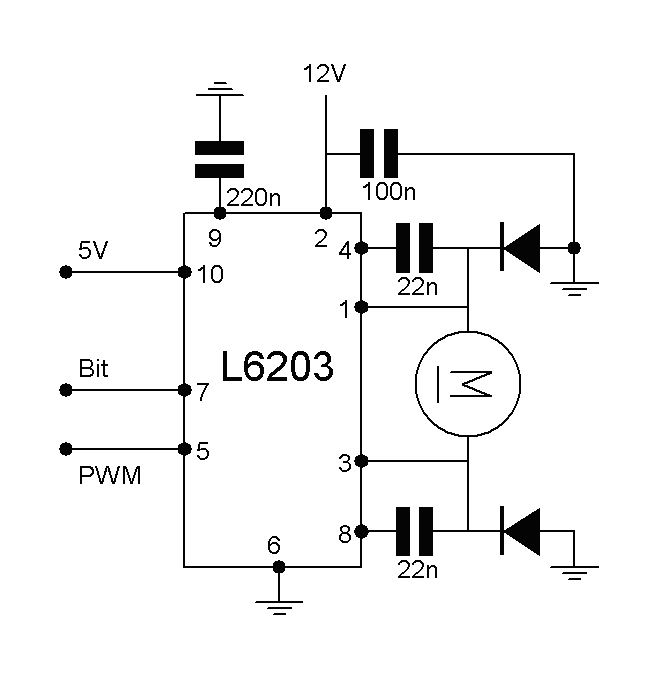
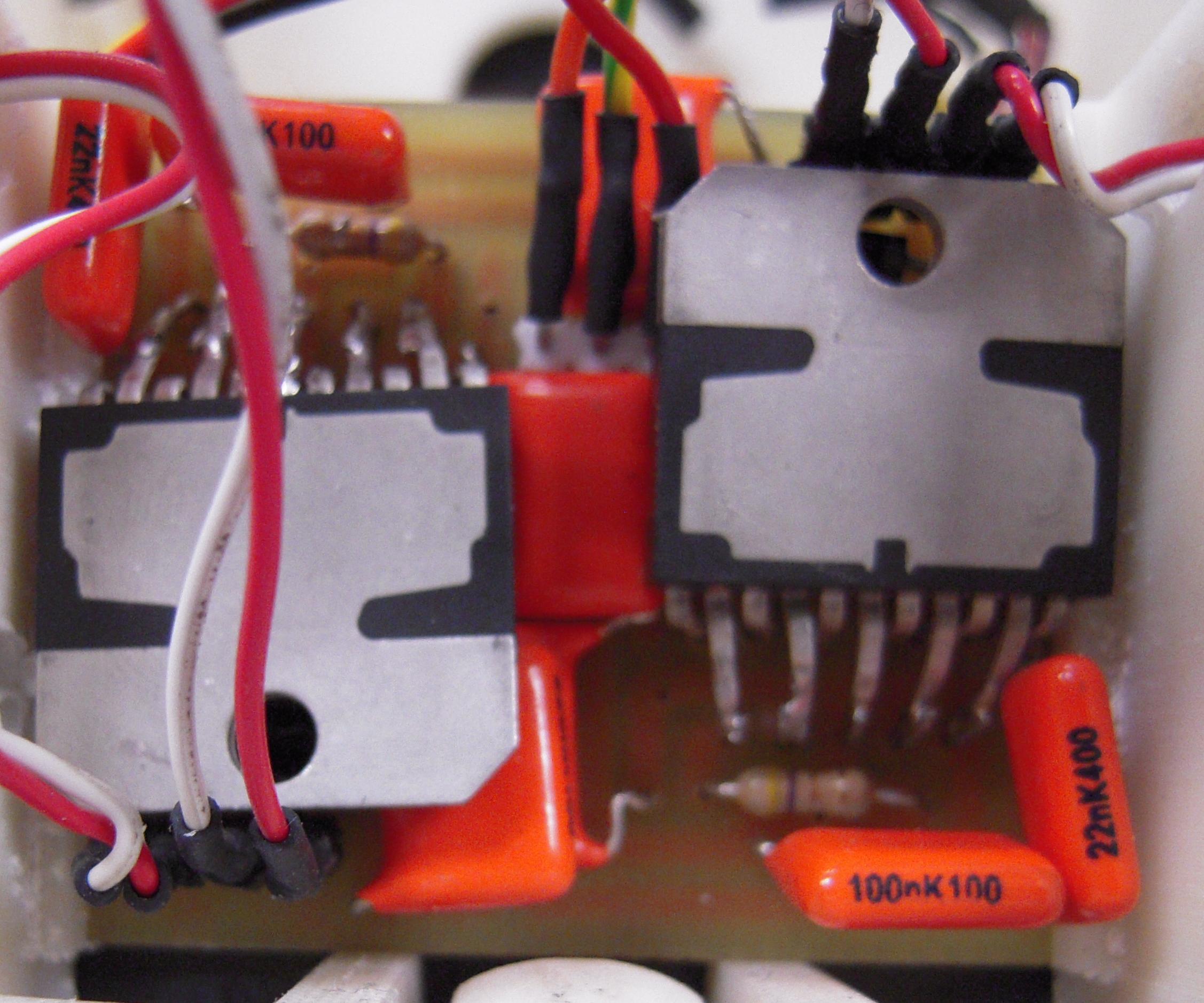
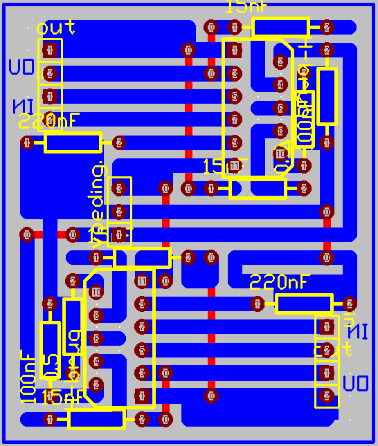
To make the robot move, two 12V DC electro motors with gearbox were placed into the robot. The motors were each separately navigated with a PWM output of the microcontroller. However, the microcontroller could not provide the needed current and it is impossible to invert the motors. So a H-bridge (L6203) was integrated into the circuit. The H-bridge converts the PWM signal into voltage between 0 and 12V. By changing the second input of the H-bridge, the output voltage of the H-bridge is inverted.
Copyright © 2009 • Ward De Paepe • All Rights Reserved |