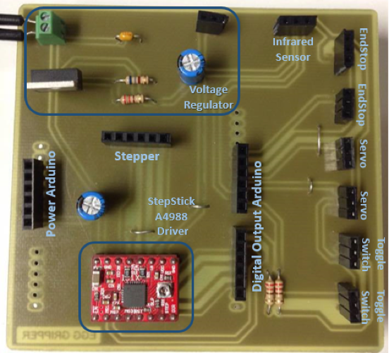
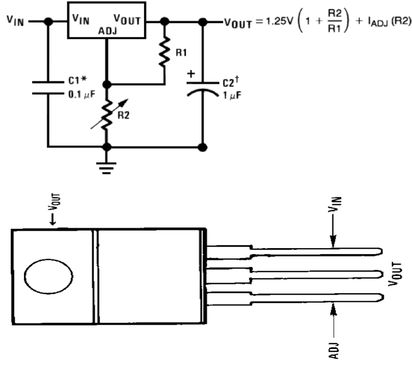
Global Overview PinLayout

Initially a global overview is given of all the components connected to the Arduino Uno. The way they work and are supplied is discussed in every part separately.

The first big issue is that a part of the electronical circuit such as the Arduino and the stepper, needs to be supplied with 8V while another part with 5 V. One could use two voltage sources but a better option is to make a voltage regulator that will transform this 8 V to 5 V.

Voltage regulator

The critical component used is the LM338. By choosing R2/R1 equal to 3 one can easily regulate the voltage from 8 V to 5 V. The main purpose of the capacitors is to create a more stable output when for example the input is noisy or when the current drawn changes significantly. In this application the voltage drop due to the current coming from pin ADJ is negligible.

It is important to notice that this supply is a dissipative power supply. This means that the difference in voltage between the input and output multiplied by the output current will be dissipated into heat. This heat can be absorbed using a heat sink but since the dissipated power is not big (Pmax = 3 V*2 A= 6 W) and not everything works continuously, this is not necessary.

Stepper motor

The used (unipolar) stepper motor is the CBA45-1101 Tokyo Electric Co. This stepper is used to lower and to raise the platform. For extra information about the stepper one can go to the following website: http://www.motors.wrobots.com/CBA45-1101.php. By applying current in a specific order into the coils of the stepper, the stepper will start turning: the magnetic fields created by the injected currents will orient themselves in the direction of the permanent and fixed magnetic field of the stepper motor.

StepStick A4988 Driver

By controlling the digital outputs connected to the driver, this driver will control the current sent to the coils of the stepper. The Arduino is also isolated from the high circuit which will prevent any damage to the Arduino. By tuning the potentiometer of the chip, one can regulate how much current will be injected in the stepper and thus how much torque it will be able to apply on the axis.

Hacked servo

The servos (Futuba S3003) are used to open and close the fingers of both grippers. Initially the rotation of the servo is limited between 0° to 180°. This is done by a potentiometer and a mechanical block mechanism. Since the closing of the grippers has to be controlled, this restriction should to be removed in order to control the opening and closing of the grippers (position control).

By adding a linear potentiometer attached to the platform one can control the opening and closing of the gripper since this is linked to the height of the platform. The output of this potentiometer can be read with an analog input and like this the position can be controlled. Another way of doing this is by checking the height at which the gripper is closed and opened ("calibration"). The opening and closing angle found by calibration are respectively 60° and 165°.

Endstop

It is important to notice that the stepper motor is controlled in open loop. This means that one never knows what the position is of the platform. By adding endstops, one can initially give the command to the stepper to raise the platform and when touching the upper endstop, the exact position is known. By lowering the platform and touching the bottom endstop the signal is given to start the gripping and the release of the different grippers.

Initially the common pin will be connected internally to the ground. Once the endstop is pushed, the common pin will be connected to 5 V. The Arduino will read LOW and HIGH respectively. This signal will be used to start closing or opening the fingers of the gripper depending of the situation.

Toggle switch

Two toggle switches were implemented. The first is the on and off button that can also be used as an emergency switch. The second toggle is to switch between the automatic program and the remote controlled program in the Arduino. This remote controlled part is very useful since for tuning, troubleshooting, maintenance,etc one can easily control the position of the platform and the opening/closing of the fingers of the grippers. The working principle of the used toggle switches is identical to that of the endstop.

Infrared sensor

Depending on which button you push a certain hexadecimal code is read by the digital output. By linking the different codes to specific commands, the egg gripper can be remote controlled.

PCB design

The PCB is designed using the software Eagle. The first part of the design consists of making a scheme of the circuit and afterwards this is translated into placing different components on a board. A big restriction was the fact that the PCB should be designed on one side. This means that overlap had to be avoided to minimize the amount of jumpers. The blue part represents the bottom layer of the PCB. The red cables represent the jumpers that are soldered at the end on the PCB. A terminal block for an external 5 V supply was implemented in the PCB design in case of failure of the voltage regulator. Male headers are used to place the PCB on the Arduino and female headers are used to connect the components attached to male headers to the PCB.

After soldering all the components on the PCB, the printed circuit board is ready to use.