Introduction

In order to develop the GripEgg, mainly two parts must be designed, i.e. the grippers themselves and the structure to provide the upward and downward movement. For both parts, specific pieces are designed with use of the commercial software Solidworks. The development of the different mechanical parts are explained below. Furthermore, The printed pieces can be seen by clicking on the corresponding CAD images.

Flexible fingers

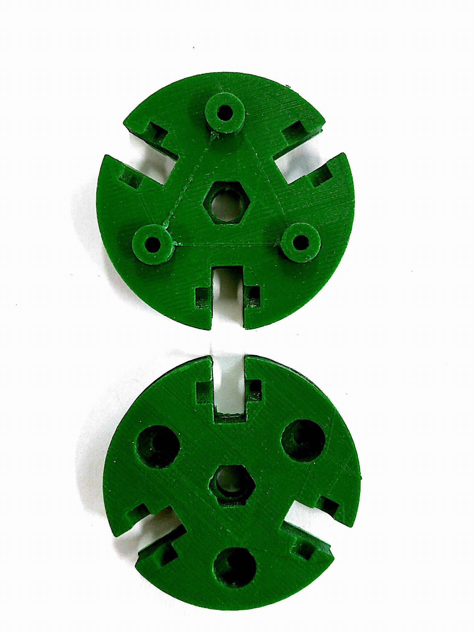
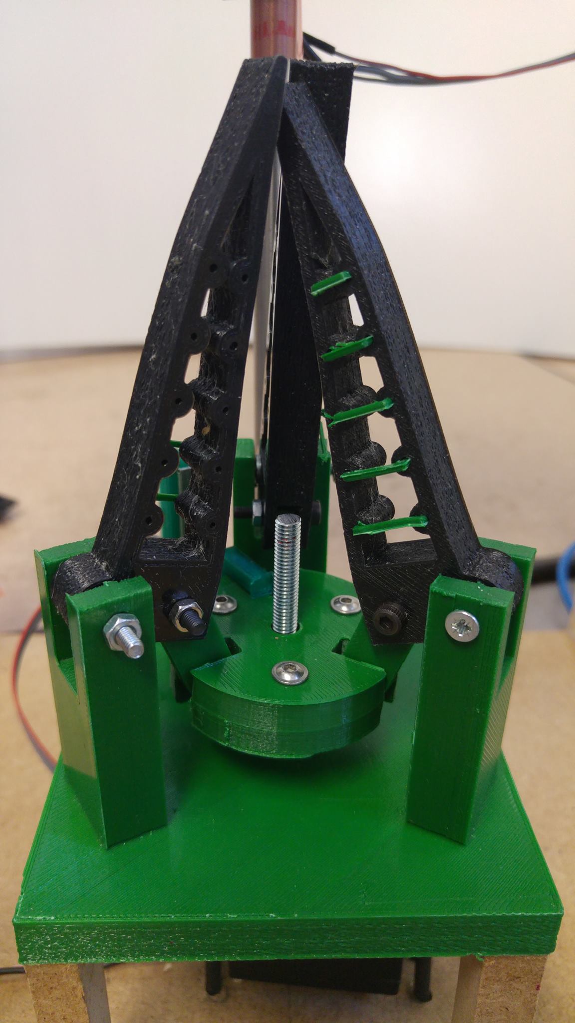
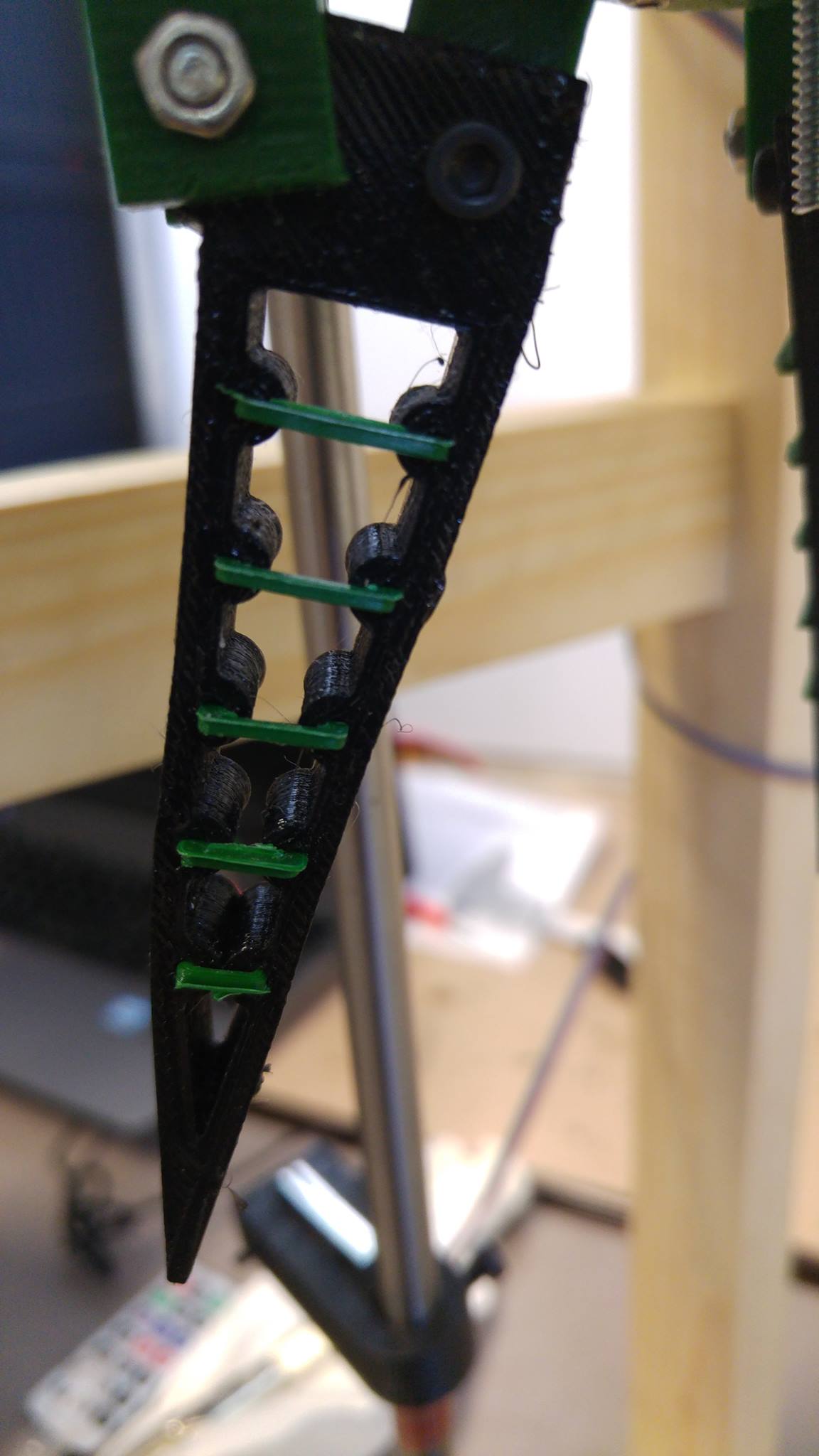
For the GripEgg, a gripper is developed to fetch an egg without breaking it. This means that a solution must be found regarding the existing grippers whose handle is too firm to perform this action. The most important part of the gripper to be designed is the set of fingers. The idea for the development of these fingers consists in the use of a flexible material. To make sure that the egg does not fall out of these fingers, some pieces with a high stiffness are added horizontally to the flexible material.

Gripper base

For what regards the rest of the gripper part, the fingers are attached to a small base which can perform an up- and down-movement due to a screw mechanism that is connected to a servo motor. This allows the fingers to open and close. The small base is designed in two parts such that a nut can be placed in the middle where the screw is threaded in. Once the egg is gripped, this screw mechanism allows the egg to rest in the fingers, without consuming any energy.

This model of the gripper is used for the bottom gripper as well as the gripper that moves up and down. The bottom gripper is mounted on a small table-like structure in order put the servo motor underneath it. For the upper gripper, the same idea is used.

Gripper

This model of the gripper is used for the bottom gripper as well as the gripper that moves up and down. The bottom gripper is mounted on a small table-like structure in order to put the servo motor underneath. For the upper gripper, the same idea is used.

Connection servo/screw

Another important part for the working of the opening and closing of the gripper is the connection between the servo motor and the screw. The piece that ensures this connection is also designed in two separate pieces such that the screw can be blocked in between them.

Structure

To ensure a smooth up and down motion of the upper gripper, pulleys and belts are used. The challenge with this method is to find an adequate way to connect the upper gripper with these belts. Also, a transmission must be developed between one pulley and the rest of the pulleys since only one stepper motor is used and thus motion is only transmitted to one pulley.

Basically, the up and down movement should be performed by the use of two belts and four pulleys. But since only one stepper is used and thus only one pulley can be set into a rotary motion, a solution has to be designed. Therefore the idea for the transmission of motion is done by implementing a third belt, and by making the single pulleys at the top of the structure double ones, this problem is solved.

Pulley

Keeping in mind that there is always a limit on the budget, the best solution is to 3D-print the pulleys instead of buying them. Therefore the pulleys are designed optimally for the application of the egg gripper, i.e. with an outer diameter of 3 cm and pitch of 0.5 cm.

Tensioning mechanism

Once the pulleys are designed, supports are needed to attach them to the structure, but these parts also have another functionality that is very important: the tensioning of the belts. The idea is to be able to push the axis down on which the pulleys are mounted by means of a screw mechanism, at the bottom of the structure for the tensioning of the two side belts. The same idea is applied for the third belt, although there the direction in which the axis of the pulley can be pushed, is sideward since it is mounted on the top part of the structure.

Platform supports

To attach the platform for the upper gripper to the belts, special parts are designed based on the clamping of the belt in those parts. Since the parts of the belt closest to the corresponding sides of platform do not move in the same direction, a special part is designed to be attached to the outer belt part, where the inner belt part can freely move through. In this way, the smooth up and down movement of the platform is ensured.

Guide & linear bearing

With the attachment pieces of the belts to the upper gripper platform, its stability is not ensured since it can still tilt in the direction orthogonal to the attachments to the belt. Therefore a vertical bar is placed over the height of the structure, on which the platform can slide up- and downwards. A linear bearing is added between the platform and bar to obtain a frictionless and easy movement.